44
LP-179 REV. 11.26.14
PART 7 – GAS CONNECTIONS
Failure to follow all precautions could result in fire, explosion, severe injury or death!
The gas supply shall have a maximum inlet pressure of less than 14"
water column (350 mm), ½ pound pressure (3.5 kPa), and a minimum of
3.5" water column. The entire piping system, gas meter and regulator
must be sized properly to prevent pressure drop greater than 0.5" WC as
stated in the National Fuel Gas Code. This information is listed on the
rating plate.
It is very important that you are connected to the type of gas as noted on
the rating plate: "LP" for liquefied petroleum, propane gas, or "Nat" for
natural or city gas. All gas connections must be approved by the local
gas supplier or utility, in addition to the governing authority, prior to
turning the gas supply on.
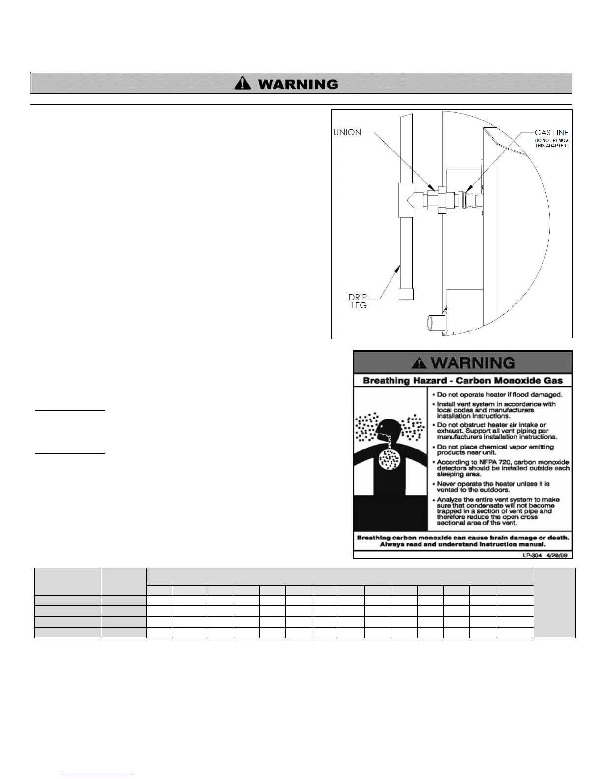
Do not remove the adaptor in Figure 26! It is mandatory that this fitting is
used for connection to a field fabricated drip leg per the National Fuel
Gas Code. You must ensure that the entire gas line to the connection at
the water heater is no smaller than ¾".
Once all inspections have been performed, the piping must be leak
tested. If the leak test requirement is a higher test pressure than the
maximum gas inlet pressure, you must isolate the heater from the gas
line to continue leak testing. To do this, you must turn off the factory and
field-installed gas cocks. This will minimize the possibility of damaging
the gas valve. Failure to do so may damage the gas valve. In the event
the gas valve is exposed to a pressure greater than ½ PSI, 14" water column,
the gas valve must be replaced. Never use an open flame (match, lighter, etc.)
to check gas connections.
A. GAS PIPING
Run the gas supply line in accordance with all applicable codes. Locate and
install manual shutoff valves in accordance with local and state requirements.
B. GAS TABLE
Refer to the table below to size the supply piping to minimize pressure drop
between meter or regulator and unit.
Maximum capacity of pipe in cubic feet of gas per hour for gas pressures of .5
psi or less and a pressure drop of .3 inch water column.
Nominal Iron
Pipe Size (In.)
Table 10 – Source – ANSI Z223.1
It is recommended that a soapy solution be used to detect leaks. Bubbles will appear on the pipe to indicate a leak is present. The gas
piping must be sized for proper flow and length of pipe to avoid excessive pressure drop. Both the gas meter and the gas regulator
must be properly sized for the total gas load. If you experience a pressure drop greater than 1" WC, the meter, regulator or gas line is
undersized or in need of service. You can attach a manometer to the incoming gas drip leg by removing the cap. The gas pressure
must remain between 3.5" WC and 14" WC during stand-by (static) mode and while in operating (dynamic) mode at full output.
Figure 26 – Phoenix Gas Connection - LP-179-Q
 Loading...