62 |
Anschlussbeispiel
8.4 TF-Schalter
Beispiel:
Lüfter soll bei einer Innentemperatur von 35 °C
und einer relativen Luftfeuchte von 70 % und wenn
die Außentemperatur unter 30 °C und die relative Feuchte unter 60 % fällt, einschalten.
Einstellungen: T1 Ein = 35 °C, T1 Aus = 34 °C
Einstellungen: F1 Ein = 70 % , T 1 Aus = 60 %
Einstellungen: T2 Ein = 30 °C , T2 Aus = 31 °C
Einstellungen: F2 Ein = 60 %, F2 Aus = 70 %
Hinweis: Der Feuchtesensor T1 wird im Raum montiert
Der Feuchtesensor T2 wird außen montiert
Netz 230V/50 Hz
The parameters have the following meaning:
T1 EIN
The switch-on temperature controls at which temperature the relay T1 should
be switched on.
Setting range: -40°C to +120°C
Factory setting: 23°C
Example:
Fan should switch on at an indoor temperature of 35°C and
a relative humidity of 70 % and when the outside temperature falls
below 30°C and the relative humidity below 60%.
Settings T1 On = 35°C, T1 Off = 34°C
Settings F1 On = 70 %, F1 Off = 60 %
Settings T2 On = 30°C, T2 Off = 31°C
Settings F2 On = 60 %, F2 Off = 70 %
Note: Sensor T1 is installed inside the room
Sensor T2 is to be installed outside
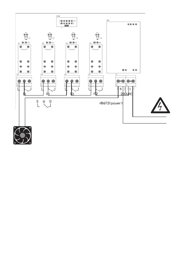
Connection example:
Mode 7.4 „TF switch“
Supply air
(fan 230~)
Mains 230V/50Hz
S = normally open contact
W = change-over contact
O
= normally closed
contact
Modes/ functions
L(Phase)
N(Zero)
 Loading...