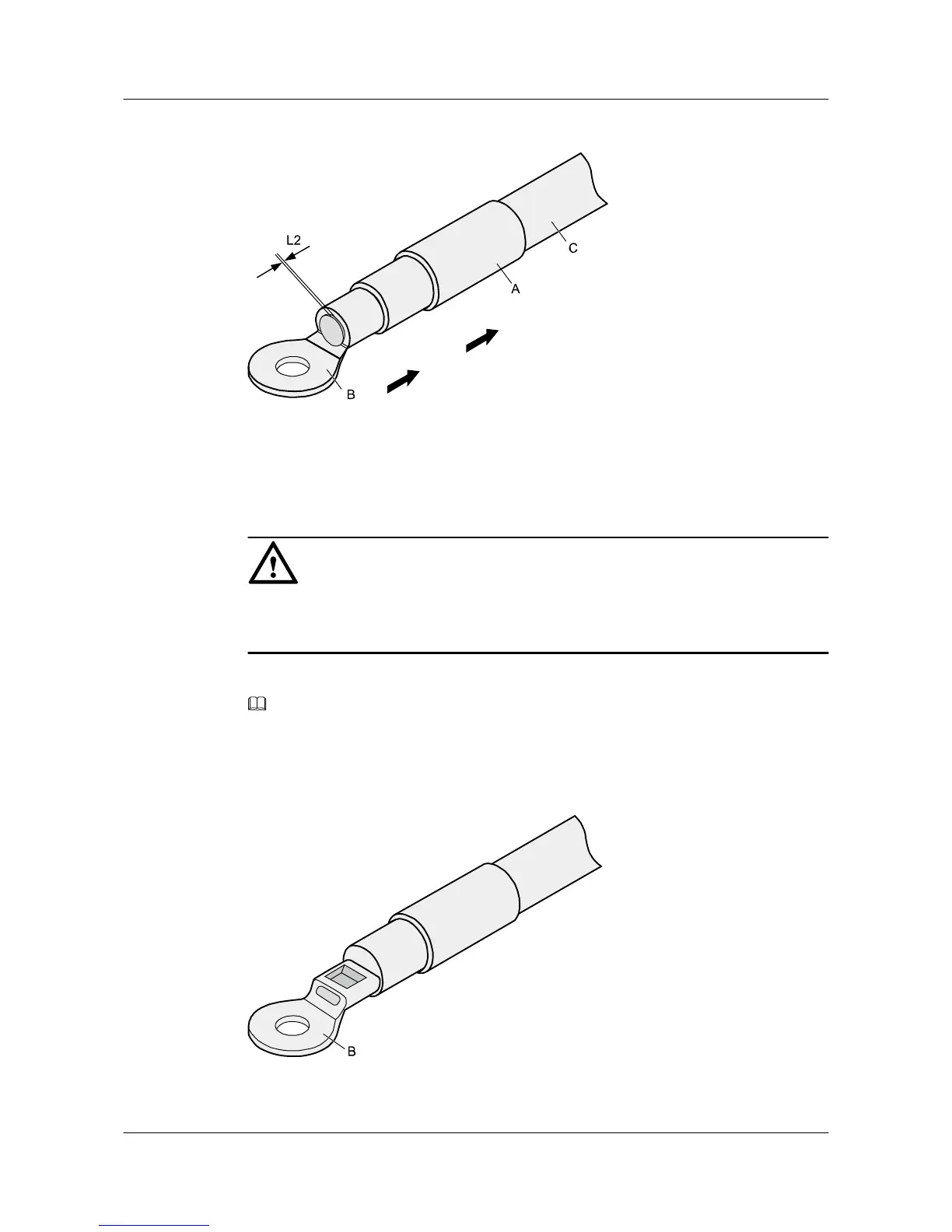
Figure 5-3 Putting the heat shrink tubing onto the bare crimping terminal
Step 3 Put the OT terminal B onto the exposed conductor, and ensure that the OT terminal is in good
contact with the insulation coating C, as shown in Figure 5-3.
NOTICE
After the conductor is fed into the OT terminal, the protruding part of the conductor, or L2 in
Figure 5-3, must not be longer than 2 mm (0.08 in.).
Step 4 Crimp the joint parts of the bare crimping terminal and the conductor, as shown in Figure 5-4.
NOTE
The shapes of crimped parts may vary with the crimping dies.
Figure 5-4 Crimping the joint parts of the bare crimping terminal and the conductor (OT
terminal)
Huawei AP8030DN & AP8130DN
Hardware Installation and Maintenance Guide
5 Appendix
Issue 02 (2014-12-05) Huawei Proprietary and Confidential
Copyright © Huawei Technologies Co., Ltd.
47