Table 5-3 Mapping between the cross-sectional area of the conductor and the value of L1
Cross-
Sectional Area
of Conductor
(mm
2
(in.
2
))
Value of L1 (mm
(in.))
Cross-Sectional
Area of Conductor
(mm
2
(in.
2
))
Value of L1 (mm
(in.))
1 (0.002) 8 (0.31) 10 (0.015) 15 (0.59)
1.5 (0.002) 10 (0.39) 16 (0.025) 15 (0.59)
2.5 (0.004) 10 (0.39) 25 (0.039) 18 (0.71)
4 (0.006) 12 (0.47) 35 (0.054) 19 (0.75)
6 (0.009) 14 (0.55) 50 (0.077) 26 (1.02)
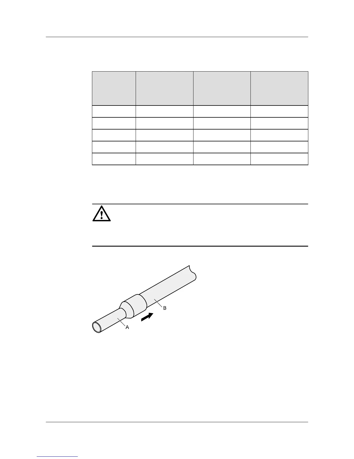
Step 2 Putting the cord end terminal onto the conductor, and ensure that the conductor is aligned with
the edge of the cord end terminal, as shown in Figure 5-13.
NOTICE
After the conductor is fed into the cord end terminal, the protruding part of the conductor must
not be longer than 1 mm (0.04 in.).
Figure 5-13 Put the cord end terminal onto the conductor
Step 3 Crimp the joint parts of the cord end terminal and the conductor, as shown in Figure 5-14.
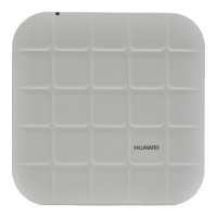
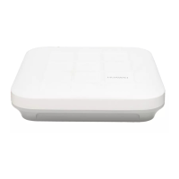
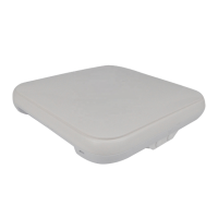
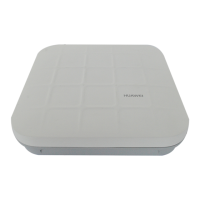
Huawei AP8030DN & AP8130DN
Hardware Installation and Maintenance Guide
5 Appendix
Issue 02 (2014-12-05) Huawei Proprietary and Confidential
Copyright © Huawei Technologies Co., Ltd.
52