l Crossover cables are connected in a crossover manner. They are used to connect terminals
such as two computers or switches. Table 5-8 lists the connections of core wires in a
crossover cable.
Table 5-8 Connections of core wires in a straight crossover cable
RJ45 Connector 1 RJ45 Connector 2 Core Wire Color Twisted or Not
6 2 Orange Twisted
3 1 Orange-White
2 6 Green Twisted
1 3 Green-White
4 4 Blue Twisted
5 5 Blue-White
8 8 Brown Twisted
7 7 Brown-White
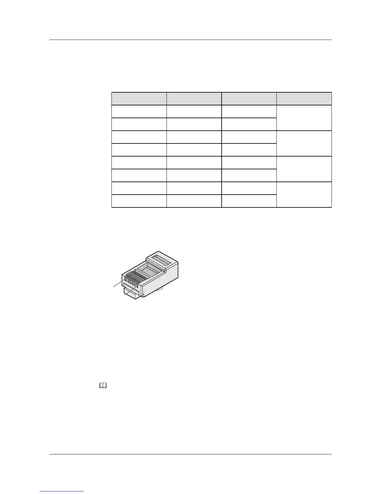
Figure 5-38 shows the pins of an RJ45 connector.
Figure 5-38 Pins of an RJ45 connector
Procedure
Step 1 Feed both connectors of the cable into the ports of the cable tester.
Step 2 After the connectors are properly inserted, turn on the tester. If the indicators from 1 to G turn
on simultaneously, you can infer that the pins work normally and the wires are correctly
connected.
NOTE
Turn the switch to the S position to slow down lighting of the indicators so that you can see the indicators
more clearly, as shown in Figure 5-39.
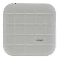
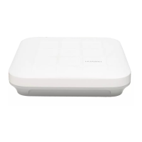
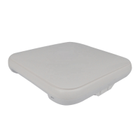
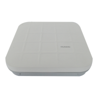
Huawei AP8030DN & AP8130DN
Hardware Installation and Maintenance Guide
5 Appendix
Issue 02 (2014-12-05) Huawei Proprietary and Confidential
Copyright © Huawei Technologies Co., Ltd.
65