Dehydrator alarms
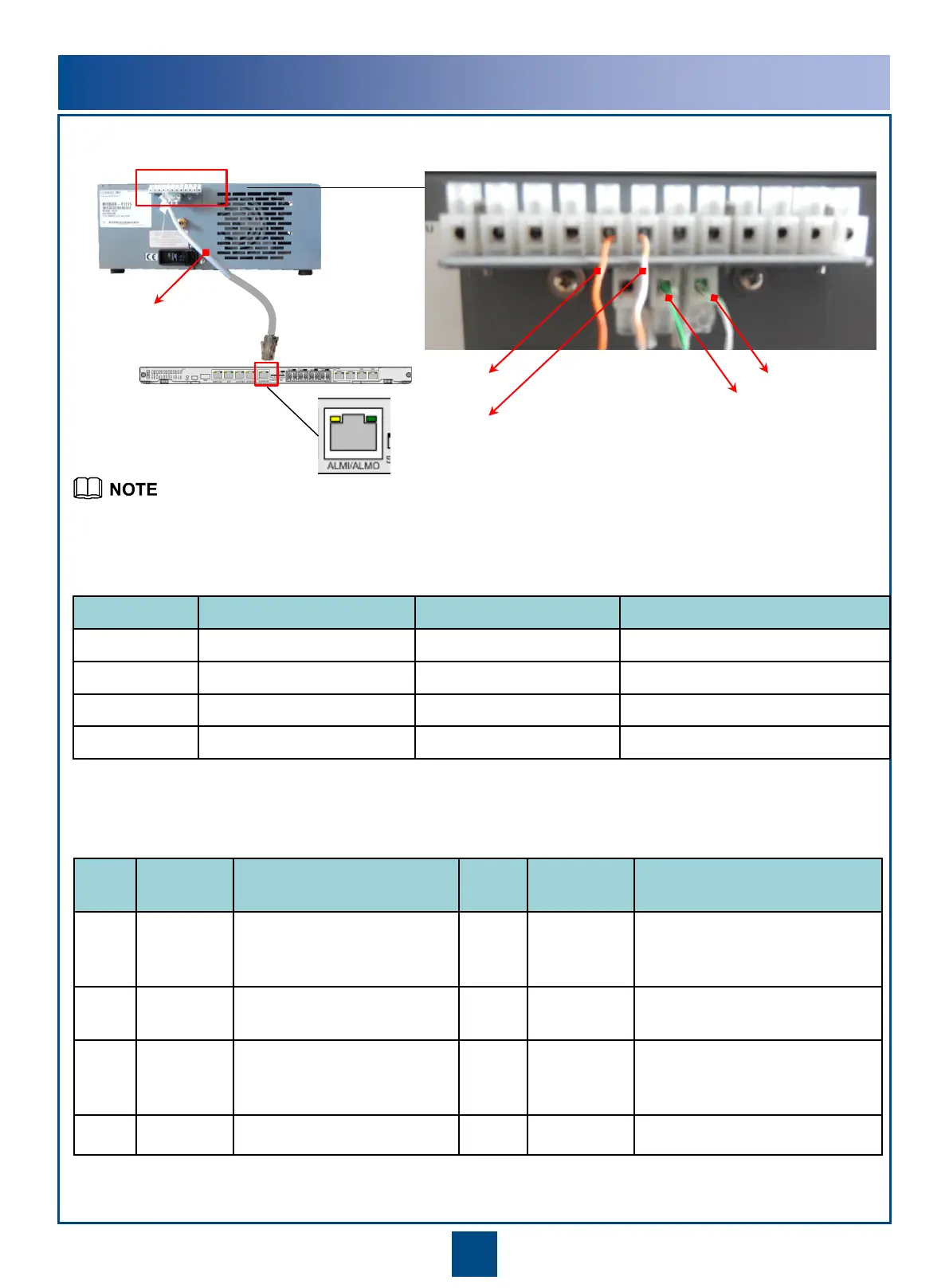
Pin assignments of the alarm port on the system control board of RTN 980 L
•Install the alarm signal cable based on the interface-cable mappings and pin assignments described in the tables
above.
12 11 10 9 8 7 6 5 4 3 2 1
15 14 13
System control
board of the IDU
Alarm signal cable
Orange
Orange and white
Green and white
Green
Port No. Wire Color Alarm Peer Pin in the Alarm Port
7 Orange and white POWER FAIL NO 1
8 Orange POWER FAIL COM 2
13 Green and white SUMMARY NO 3
14 Green SUMMARY COM 6
Pin
No.
Wire
Color
Alarm Output Pin
No.
Color Alarm Output
1 Orange
and
white
Alarm signal input 1 5 Blue and
white
Ground end of alarm signal
input 3
2 Orange Ground end of alarm
signal input 1
6 Green Ground end of alarm signal
input 2
3 Green
and
white
Alarm signal input 2 7


 To Next Page