(9) DC switch 3 (DC SWITCH 3) (10) Ventilation valve
(11) USB port (12) Communications port (COM)
(13) Hole for the AC output power cable (14) Hole for the tracking system power cable
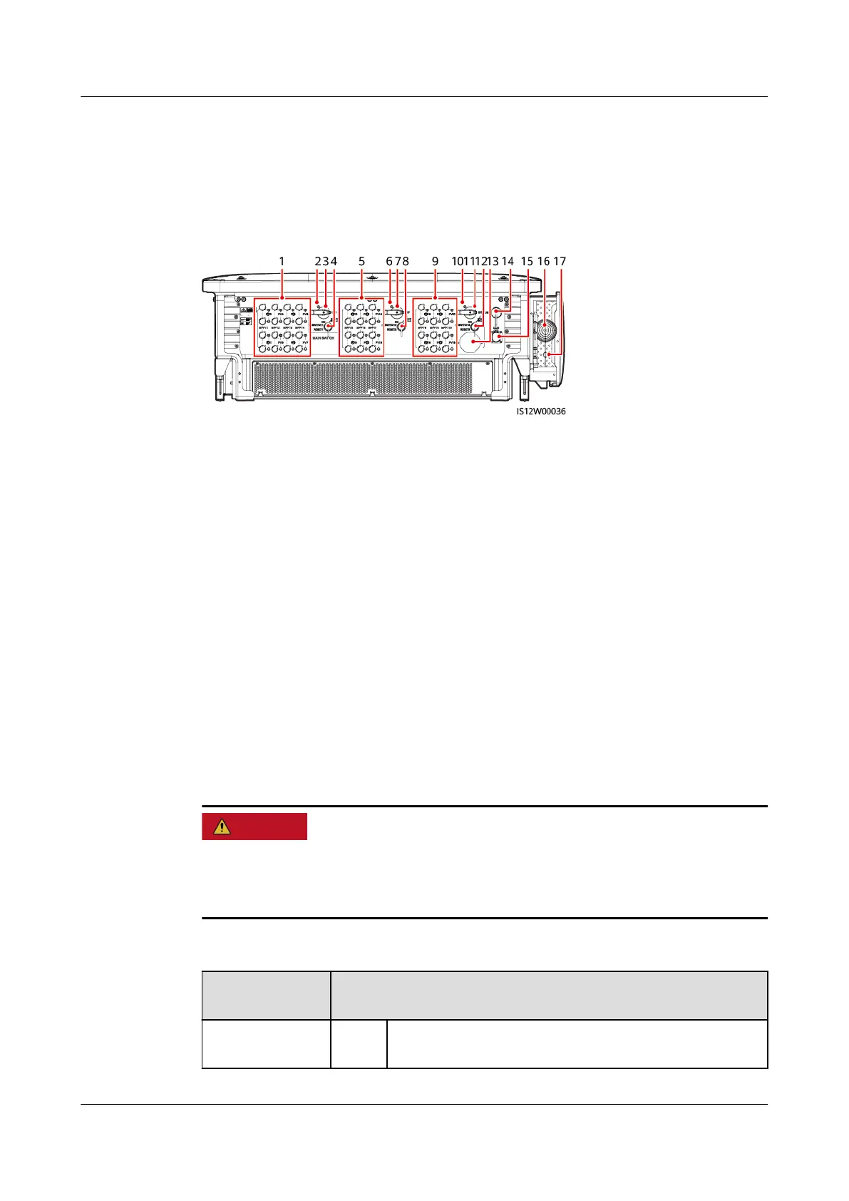
Figure 2-8 Port description (automatic DC switch)
(1) DC input terminal group 1 (PV1–PV8,
controlled by DC SWITCH 1)
(2) (Optional) Screw hole for DC switch 1
(3) DC switch 1 (DC SWITCH 1) (4) Reset button 1 (RESET 1)
(5) DC input terminal group 2 (PV9–PV14,
controlled by DC SWITCH 2)
(6) (Optional) Screw hole for DC switch 2
(7) DC switch 2 (DC SWITCH 2) (8) Reset button 2 (RESET 2)
(9) DC input terminal group 3 (PV15–PV20,
controlled by DC SWITCH 3)
(10) (Optional) Screw hole for DC switch 3
(11) DC switch 3 (DC SWITCH 3) (12) Reset button 3 (RESET 3)
(13) Ventilation valve (14) USB port
(15) Communications port (COM) (16) Hole for the AC output power cable
(17) Hole for the tracking system power cable -
DC Switch Description
The DC switches automatically turn o when a fault occurs in the inverters (LED4
is steady red, and the three DC switches are OFF). In this case, contact your
technical support. Do not turn on the DC switches by yourself.
Table 2-2 DC switch description
Switch
Component
Description
DC SWITCH ON The DC switch is ON and can automatically turn o
for protection.
SUN2000-(75KTL, 100KTL, 110KTL, 125KTL) Series
User Manual 2 Overview
Issue 15 (2023-01-31) Copyright © Huawei Technologies Co., Ltd. 20
 Loading...