5. Connecting PGND Cables
Good grounding for the SUN2000 can help resist the impact of the surge voltage and improve the
EMI performance. First connect the PGND cable before connecting the AC power cable, DC power
cable, and communication cable.
For the system with one SUN2000, connect the PGND cable to the ground. For the system with
multiple SUN2000s, connect the PGND cables of all SUN2000s to a ground bar in equipotential
mode.
If the installation location is near the ground, first connect the PGND cable to the ground before
installing the SUN2000 on the wall.
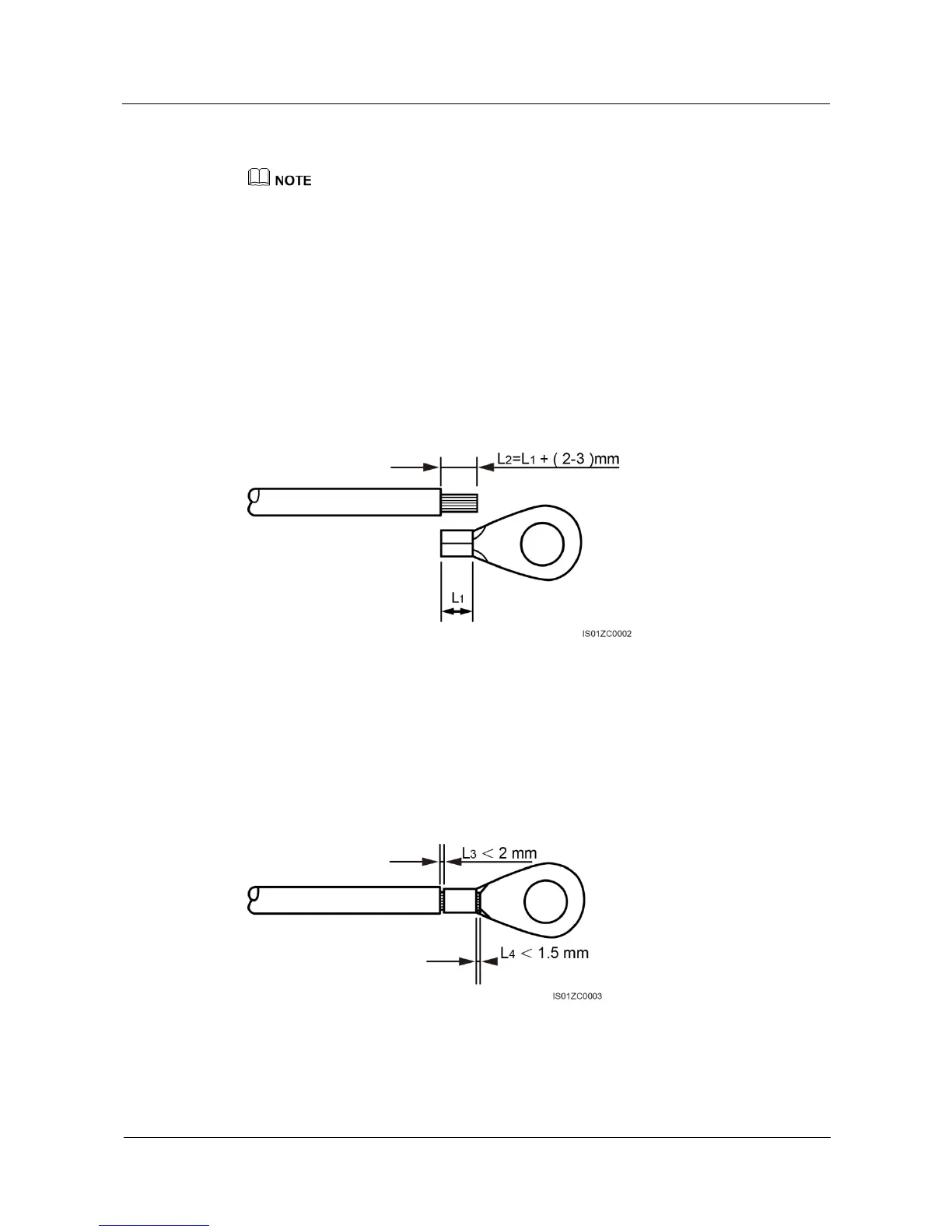
Step 1 Remove the insulation layer with an appropriate length using a wire stripper, as shown in
Figure 1-16.
10 AWG outdoor power cables are recommended for grounding purposes.
Figure 1-16 Preparing a ground cable (1)
Note: L2 is 2 to 3 mm longer than L1.
Step 2 Insert the exposed core wires into the OT terminal and crimp them by using a crimping tool,
as shown in Figure 1-17.
Recommanded OT terminals: OT M6; recommanded ground cables: with a cross sectional
area of larger than or equal to 6 mm
2
.
Figure 1-17 Preparing a ground cable (2)
Note 1: L3 is the length between the insulation layer of the ground cable and the crimped part.
L4 is the distance between the crimped part and core wires protruding from the crimped part.
 Loading...