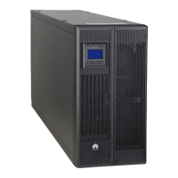
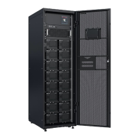
Figure 6-1 Conceptual diagram (using two parallel UPSs as an example)
Procedure
Step 1 Check before power-on: Ensure that the mains input, bypass input, and AC output
cables of each UPS in the parallel system are connected in the same phase
sequence.
1. Check that the general mains input, bypass input, and output circuit breakers
are OFF.
2. Check that the power cables of UPSs are connected in parallel (the external
mains input, external bypass input, and external output power switches for
each UPS are ON).
3. Use a multimeter to measure the impedance between phases A, B, and C of
the mains/bypass input and AC output of any UPS. If the measured result is
low conducted resistance, check whether the cables to each UPS are short-
circuited.
4. Use a multimeter to measure the impedance between phases A, B, and C of
the mains/bypass input and AC output of any two UPSs. If the measured
result is low conducted resistance, check whether the mains/bypass input and
AC output phase sequences of the two UPSs are correct.
Step 2 Trigger EPO on each UPS.
1. Press the EPO switches connected to the dry contact cards of all UPSs one by
one, or remove the 4-pin terminals from the EPO ports on the dry contact
cards of all UPSs, or press the general EPO switch.
2. If a single UPS is not powered o after commissioning, verify on the
monitoring screen that EPO has been activated successfully.
UPS5000-A-(30 kVA-120 kVA)
User Manual 6 Parallel System Commissioning
Issue 17 (2024-02-21) Copyright © Huawei Digital Power Technologies Co., Ltd. 132

 Loading...
