SR05-D1A3-PV manual v1801 29/83
2) Hold SR05 in one hand, the ball levelling mount in the other.
3) Separate SR05 from the ball levelling mount by gently pulling out the ball levelling
mount.
4) Mount the ball levelling to a surface or platform with its M5 bolts and nuts. See
chapter on tooling required.
5) Place SR05 on the ball levelling mount by gently pushing the sensor onto the ball
head until it clicks.
6) SR05 can now be rotated 360 ° on its ball head by hand. This rotation allows easy
cable orientation adjustment. It can be tilted up to 10 °. This allows angle
compensation on non-horizontal surfaces up to 10 °.
7) When SR05 is mounted and levelled, judging by its bubble level, lock the ball head
mechanism by turning the set screw clockwise with the 4 mm hex key until it is
tightened. SR05 is now locked in its position.
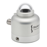
A similar approach is followed when levelling SR05 on its tube mount in the field:
1) judge bubble level and cable orientation 2) loosen set screw to tilt and rotate SR05
3) tighten set screw to lock ball levelling 4) SR05 is mounted and levelled
Figure 5.4.2 Levelling steps for SR05 when mounted on tube mount with ball levelling
 Loading...