SR05-D1A3-PV manual v1801 62/83
8.2 Trouble shooting
Table 8.2.1 Trouble shooting for SR05 (continued on next page)
Inspect the instrument for any damage.
Inspect if the connector is properly attached.
Check the condition of the connectors (on chassis as well as the cable).
Inspect if the sensor receives DC voltage power in the range of 5 to 30 VDC.
Inspect the connection of the shield (typically not connected at the network side).
Inspect the connection of the sensor power supply, typically the negative is
connected to the network common.
Install the Sensor Manager software on a PC. Equip the PC with RS-485 for
communication with SR05-D1A3-PV. Put DC voltage power to the sensor and
establish communication with the sensor. At power–up the signal may have a
temporary output level different from zero; an offset. Let this offset settle down.
The sensor
does not give
any signal
Check if the sensor reacts to light: expose the sensor to a strong light source, for
instance a 100 W light bulb at 0.1 m distance. The signal should read > 100 W/m
2
now. Darken the sensor either by putting something over it or switching off the
light. The instrument voltage output should go down and within one minute
approach 0 W/m
2
. Check the data acquisition by replacing the sensor with a spare
sensor with the same address.
Not able to
communicate
with the
sensor
Check all physical connections to the sensor and try connecting to the sensor
again. If communicating is not possible, try to figure out if the address and
communication settings are correct. Analyse the cable performance by measuring
resistance from pins to cable ends. The electrical resistance should be < 10 Ω. In
case of doubt, try a new cable.
Connect sensor to a PC and perform the “Find” and “Find all” operation with the
Sensor Manager to locate the sensor and verify the communication settings. If all
physical connections are correct, and the sensor still cannot be found, please
contact the factory to send the sensor to the manufacturer for diagnosis and
service.
respond to a
request for 6
or more
registers
It is not possible to request more than five 16 bit registers in one request. In case
of requesting six or more registers in just one request, the sensor will not
respond. If requesting six or more registers, use multiple requests: the sensor will
respond as expected.
signal is
unrealistically
Note that night-time signals may be negative (down to -5 W/m
2
on clear windless
nights), due to zero offset a.
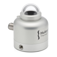
Check if the pyranometer has a clean dome.
MINIMUM RECOMMENDED PYRANOMETER MAINTENANCE (continued)
7 6 years parts
replacement
if applicable / necessary replace the parts that are most
exposed to weathering; cable, connector. NOTE: use Hukseflux
approved parts only
8 internal
inspection
if applicable: open instrument and inspect / replace O-rings;
dry internal cavity around the circuit board
high-accuracy recalibration indoors according to ISO 9847 or
outdoors according to ISO 9846
 Loading...