SR05-D1A3-PV manual v1801 30/83
When retrofitting SR05 or when ordering SR05 pyranometer and its optional ball levelling
in separate orders, the user has to ensure a shim is placed properly in the centre of the
bottom plate of SR05. The shim allows smooth levelling. Read the following chapter on
placing and removing the shim. When ordering SR05 combined with ball levelling, the
shim is already positioned in its place in the factory.
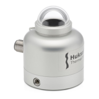
5.5 Placing and removing SR05’s ball levelling shim
Only when ordering SR05 pyranometer and its optional ball levelling separately or when
exchanging a SR05 sensor on a ball levelling mount (retrofitting), the user has to ensure
a dedicated shim is placed properly in the centre of the bottom plate of SR05. When
ordering SR05 combined with ball levelling the shim is already positioned in its place in
the factory. The aluminium shim ensures a secure fit between SR05 and ball levelling and
allows the ball head to rotate smoothly for easy levelling. The shim, a loose set screw, a
4 mm hex key, two M5x20 mounting bolts and two M5 nuts are included when ordering
the ball levelling mount separately.
Figure 5.5.1 Line drawing indicating placement of the aluminium shim and photo
showing the shim properly positioned in the centre of SR05’s bottom plate. Note the
position of the protruding ledge when placing the shim.
The shim can be placed into SR05’s bottom plate following these steps:
1) If your SR05 has a small black plastic cover cap on the countersunk set screw
opening on SR05’s side, remove it. A small flathead screwdriver may be used. Then
insert the loose set screw with a 4 mm hex key by turning the hex key clockwise
until the screw is only slightly protruding (sticking out).
2) Hold SR05 in one hand, the shim in the other.
3) Ensure the orientation of the shim fits with that of SR05’s bottom plate. Note the
position of the protruding ledge (see Figure 5.5.1).
 Loading...