13
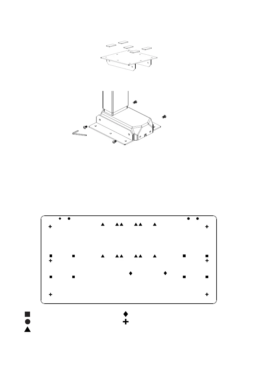
Using the (8) M6 x 10 Machine Screw Screws secure the brackets to each leg, using the 4mm
Allen Key�
Secure the (10) adhesive pads to the (2) Brackets
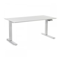
Place your worksurface upside down on a protective surface� Lift and place the legs on top of the
worksurface� Position the leg assembly on the worksurface per the following sections:
A - Humanscale Universal Worksurface�
B - Using Your Own Work-surface� Lift and place the legs on top of the worksurface� Position
Two Column Beamless (Standard/Extended Range)
2
1
3
A - Humanscale Universal Worksurface
If using one of our Universal Worksurfaces, align the legs to the following pilot holes highlighted below�
Note: Only the four outer corner pilot holes are included for alignment�
EFLOAT GO FRAME HOLES
HAND SWITCH PILOT HOLES L&R
HS KEYBOARD TRAY (ACCESSORY)
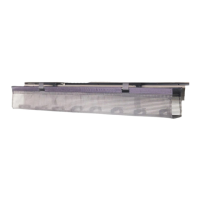
CONTROL BOX
NOT APPLICABLE WITH THIS TABLE
Please note different size tops come with different pilot hole options� More or less pilot holes may be present depending on size ordered�