nt
r
• En
ines and Transmissions
11.
The followin
is a list of components associated with
our en
nes an
transm
ss
ons
En
ine
ontrols
En
ine Monitorin
En
ine
oolin
mer
enc
qu
pmen
En
ine Exhaus
Transmission
s
hifters and Controls
11.1 En
ine
The en
ine on
our boat is at the heart of
our boat.
roper attention to and maintenance o
our en
ine
will assure
ou man
hours of pleasurable, safe
oat
n
, an
w
prevent unnecessar
en
ne pro
-
lems. You must, there
ore, become thorou
hl
amil-
iar with all aspects of the en
ines proper operation
utlined in the manufacturers
erator’s Manuals.
A
eneral maintenance pro
ram consists of proper lubri-
ation, cleanin
of fuel filters, fuel lines, and air filters.
CAUTION
! !
ake proper care when washin
down, or clean-
n
our en
nes, t
at water
oes not enter t
e a
ntakes. Water in the air intakes ma
o directl
to
the c
linders, resultin
in rust and possibl
internal
n
ne
ama
e.
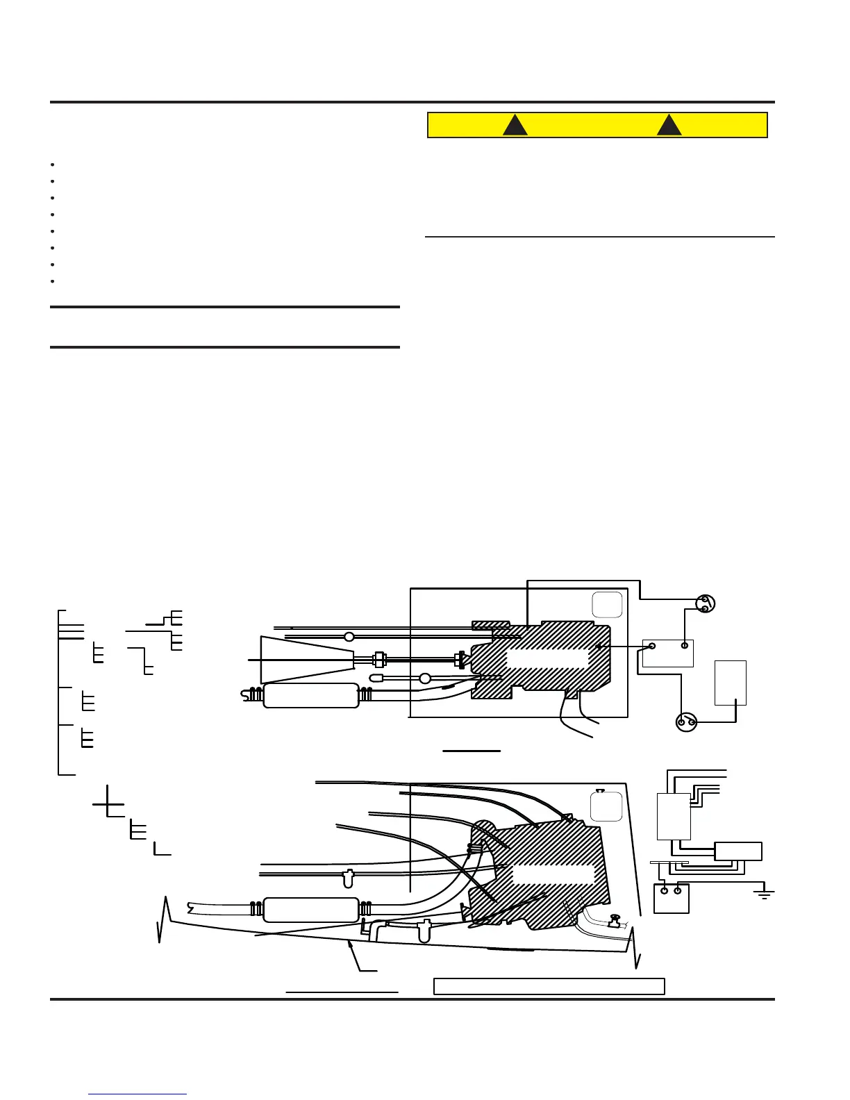
Fi
. 11.1 shows
ou drive and components aboard
our
t.
We stron
l
ur
e
ou to compl
with the manual pro-
vided b
the en
ine manufacturer. Follow the recom-
mended maintenance and warrant
schedule in the
wner’s packet. En
ine abuse or improper maintenance
ma
adversel
affect the claims made under the inde-
pendent warrant
provided b
the en
ine manu
acturer.
e en
ne manua
states t
e max
mum
rat
n
stablished b
the en
ine manu
acturer
or
our boat’s
n
ines. Do not exceed this ratin
.
heck the manual
f
r
th
r inf
rm
ti
n
t m
xim
m RPM’
.
n
ines are selected and desi
ned to meet or exceed
industr
standards set b
marine en
ine manufacturers.
HOSES TO
WATER HTR.
ENGINE
ENGINE
MUFFLER
MUFFLER
HULL BOTTOM
SYSTEMS SCHEMATIC FOR STERN DRIVE ENGINE
ENGINE
ELECTRICAL
SYSTEM
WATER INTAKE
EXHAUST
FUEL SYSTEM
FEED
RETURN
TANK
FILTER
VALVE @ TANK
RUNNING GEAR
SHAFT
COUPLING
DRIPLESS
THRU-HULL
SEA COCK
STRAINER
ELBOW
HOSE
MUFFLER
CONTROLS
SHIFT
THROTTLE
PANEL HARNESS
BATT SW
STARTING BATTERY
HOUSE BATTERY
OPT. INVERTER
12V SYSTEM
110V SYSTEM
SHORE POWER
STARTING SYSTEM
HOUSE SYSTEM
FUEL FEED & FILTER
STUFFING BOX/SHAFT
RAW WATER FEED
COMPARTMENT ENCLOSURE
COOLANT
RESV.
BATTERY
BATT. SWITCH
DC
PANEL
COOLANT
RESV.
A.C.
PANEL
SHORE PWR
TO
APPLIANCES
OPT.
BATT. CHGR.
INV.PANEL
HOSES TO
WAT.HTR.
ENGINE ENCLOSURE
RAW WTR.FEED W/STRAINER
FUEL RETURN
FUEL FEED W/FILTER
SHIFT CABLE
THROTTLE CABLE
ENGINE STOP CABLE
INSTUMT. PANEL WIRE HARNESS
CONTROL
CABLES TO
PEDESTAL
TO
FUEL
TANK
SEE ELEVATION BELOW FOR CABLES TO PEDESTAL
SEE PLAN ABOVE FOR PROP SHAFT & STUFFING BOX
NOTE: THIS DWG. IS GENERIC SCHEMATIC FORM
HEAT EXCHANGE
BLEEDER VALVE
BATTERY
(FLEX SHUT OFF)
/ INVTR.
RETURN FUEL LINE
PLAN
ELEVATION
Fi
. 11.