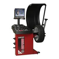
Using the DOWNWARD position, place the inner Dataset
®
arm disk edge to the
outermost location for placement of the right edge of the left adhesive weight and
enter the data by depressing the foot pedal. Refer to “Using the Auto Dataset
®
Arms,”
page 30.
Do NOT return the inner Dataset
®
arm to the “home” position.
Using the DOWNWARD position, move the inner Dataset
®
arm disk edge to the
innermost location for placement of the right edge of the right adhesive weight and
enter the data by depressing the foot pedal. Refer to “Using the Auto Dataset
®
Arms,”
page 30.
Close safety hood.
Press the green “START” button if “Hood Autostart” is disabled.
After wheel comes to a complete stop, raise the safety hood.
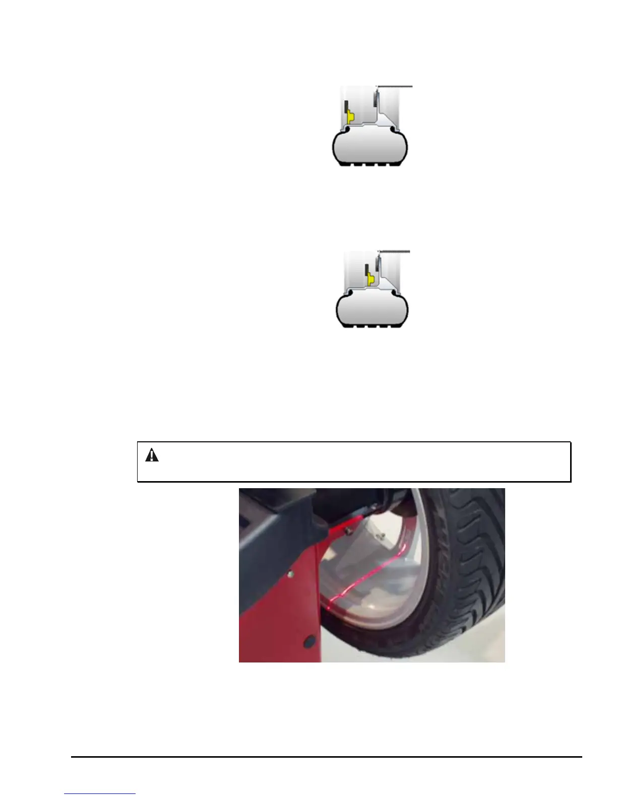
Servo-Activated Laser automatically locates BDC to aid in fast adhesive weight
positioning.
The BDC laser locator automatically displays a vivid line at bottom dead center after
a wheel has been spun. The laser turns off when the wheel is spun again.
CAUTION: Use of controls or adjustments or performance of procedures other than
those specified herein may result in hazardous radiation exposure.
With the servo enabled, attach the adhesive weight for the left weight plane using the
weight amount shown on the LCD. Refer to “Servo-Aided Adhesive Weight
Placement,” page 33. If servo is not enabled, BDC placement should be used. Refer
to “Manual Weight Position Measurement,” page 31.
GSP9200 Series Wheel Balancer Operation Instructions 3. Balancing Procedures
27
 Loading...