Fuel S
stems
The
uel s
stems aboard
our Hunter boat consists o
the
ollowin
components or sub-s
stems.
F
l T
nk
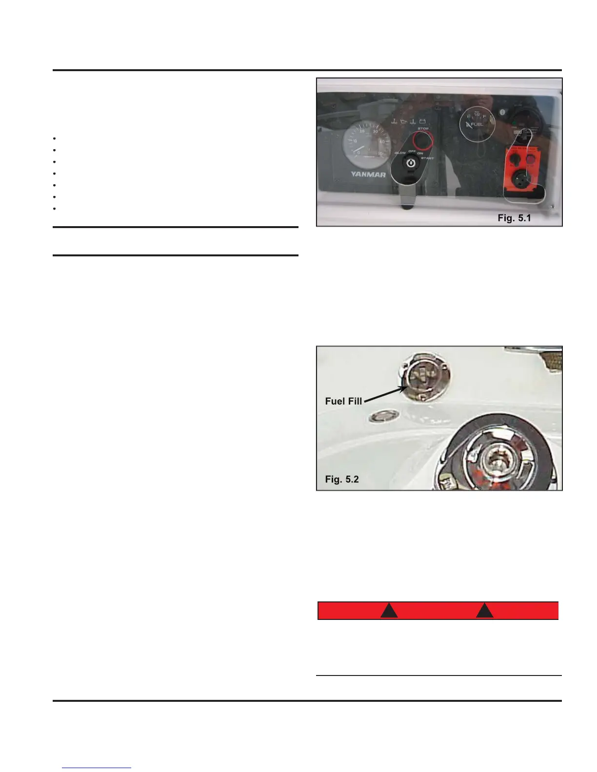
F
l Fil
n
F
l
Lin
t
r
LP
Lique
ied Petroleum
as
stem
5.1 Fuel Tanks
Your boat is equipped with a
uel tank. In the a
t state-
r
m
n
r th
nk
The tank is
illed throu
h a
uel
ill.
If
our boat has a metal or aluminum tank installed, then
the
uel tank should be inspected
or si
ns o
leaks, cor-
rosion, and/or pittin
at least once a
ear. Corrosion
normall
appears as a white, chalk
, or flak
substance
n the sur
ace o
the tank.
ometimes, it also appears
as pittin
or small pockets of missin
aluminum. Another
indication of corrosion is bubbles on the
aint that coats
the tank. I
an
o
these conditions are present, have an
authorized service technician inspect the tank immedi-
atel
. If a leak is found, turn off batter
switches and dis-
onnect shore power
ee
onnectin
Disconnectin
hore Power, AC Electrical S
stem
, which explains
t
e proper wa
to
sconnect an
sa
e an
poss
e
source o
i
nition
.
ontact
our dealer or
ustomer
ervice immediatel
.
5.1.1 Fuel Tank Capacit
Monitorin
The fuel tank is equipped with a fuel level sendin
unit, which
provides an electrical si
nal to the displa
located at the helm.
5.1.1 Fuel Tank Groundin
S
ste
The
uel tank and
uel
ill on
our boat are electricall
rounded to the en
ine ne
ative.
see the D
Electrical
hapter
. This
roundin
s
stem is desi
ned to prevent
the dischar
e o
static electricit
when
uelin
our boat.
An authorized service technician should inspect this s
s-
tem at
east once eac
ear.
5.1.2 Fuel Gau
The
uel
au
e as shown in Fi
. 5.1 is located at the
helm, and is the indicator of the fuel level in
our tank.
sua
nspect t
e rea
n
a
a
nst w
at
s s
ow-
in
in the tank to see that the
au
e is operational.
DA NG ER
! !
ever enter t
e en
ne room w
t
out proper vent
a-
ion first. A spark caused b
power tools or li
htin
ui
ment could result in fire or ex
losion which
ou
cause persona
n
ur
or
eat
nt
r
• Fuel S
stems
.