C04MUNICATI0NS SECTION 6.7
6,7, 12
VER.V09F
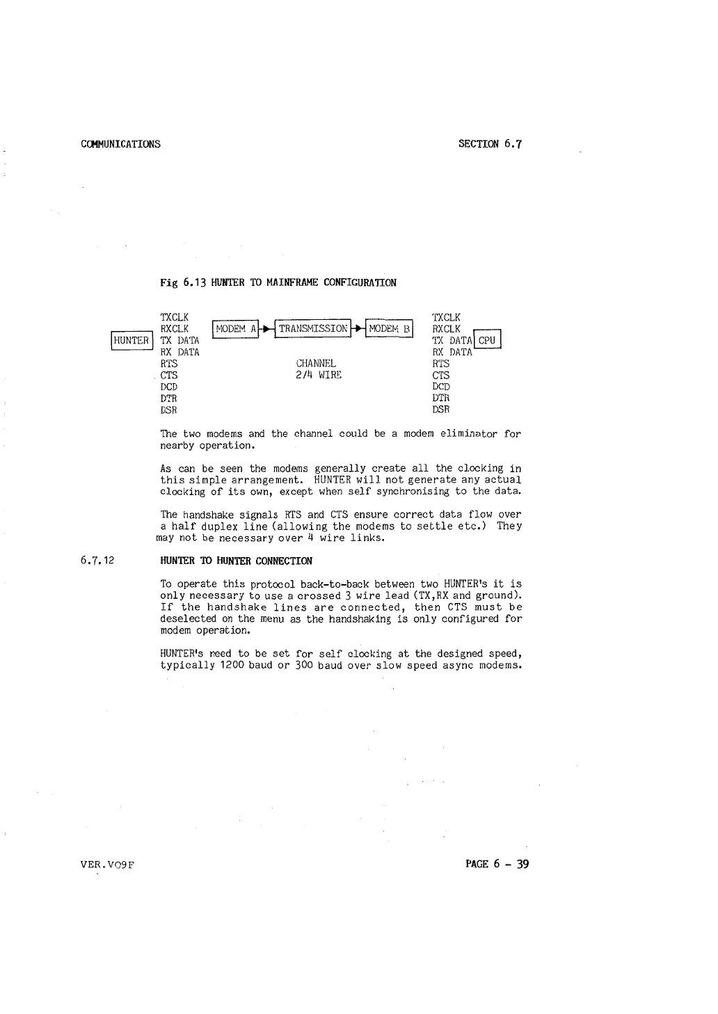
Fig 6.13 HUNTER TO MAINFRAME CONFIGURATION
TXCLK
RXCLK
TX DATA
RX DATA
RTS
. CTS
DCD
DTR
DSR
I MODEM AH TRANSMISSIO!'i H MODEM BI
CHANNEL
2/4 WIRE
TXCLK
RXCLK
r:::l
TX DATA~
RX DATA
RTS
CTS
DCD
DTR
DSR
The two modems and the channel could be a modem eliminator for
nearby operation.
As can be seen the modems generally create all the clocking in
this simple arrangement. HUNTER will not generate any actual
clocking of its own, except when self synchronising to the data.
The handshake signals RTS and CTS ensure correct data flow over
a half duplex line (allowing the modems to settle etc.) They
may not be necessary over 4 wire links.
HUNTER TO HUNTER CONNECTION
To operate this protocol back-to-back between two HUNTER's it is
only necessary to use a crossed 3 wire lead (TX,RX and ground).
If the handshake lines are connected, then CTS must be
deselected on the menu as the handshaking is only configured for
modem operation.
HUNTER's need to be set for self clocking at the designed speed,
typically 1200 baud or 300 baud over slow speed async modems.
PAGE
6 - 39