English – 37
Diagnosis and troubleshooting
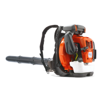
Fig 3
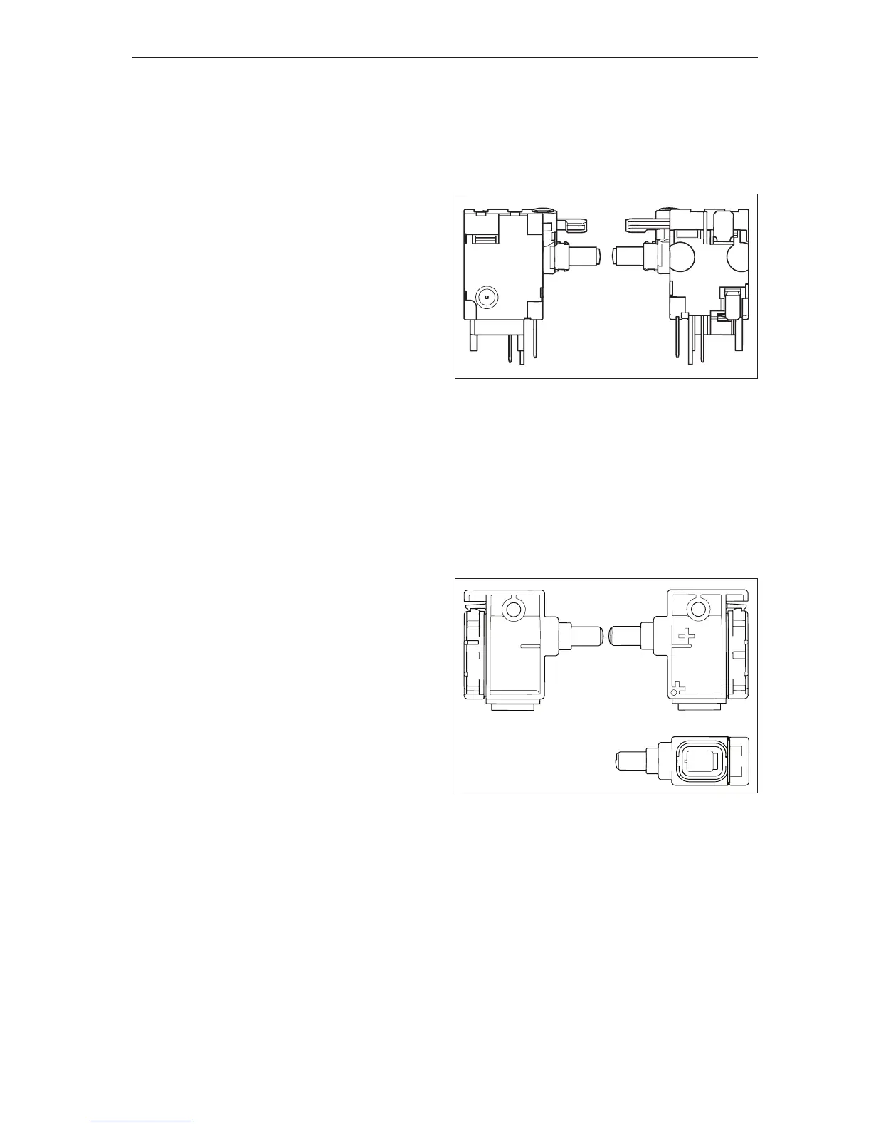
Fig 4
1 2 3 4 5 6
M1
B-
B+
B-
M
5.4 Troubleshooting the main switch
For products with S/N: -20170000000 (LiPX),
-20170000000 (LiP4), -20170000000 (LiPT5). See
gure 3.
The switch used in professional battery products
from Husqvarna has two functions, to supply cur-
rent to the control unit and the electric motor, and
act as a position sensor for the variable speed
control. All these functions can easily be tested and
veried using a resistance meter.
Note: The switch should not be depressed more
than 6 mm and not to its end position when
testing.
• Measure between B+ and B1 when the switch is
not depressed. The result should be open circuit.
• Measure between B+ and B1 when the switch is
depressed. The result should be closed circuit.
• Measure between pin 2 and pin 5 when the
switch is not depressed. The result should be
closed circuit.
• Measure between pin 2 and pin 5 when the switch
is depressed. The result should be 50kΩ ± 25 %.
• Measure between B1 and Pin 1. The result should
always be closed circuit.
If all readings are within specied limits, the switch
is OK.
For products with S/N: 20170000000- (LiPX),
20170000000- (LiP4), 20170000000- (LiPT5). See
gure 4.
Use the Common Service Tool to check the func-
tionality of the main switch.