606834CE 3-1 REV A
CZ
DA
DE
EN
ES
FR
IT
NL
PT
SV
OPERATION
Safe Operating Practices
Refer to the Safety Precautions section of this manual for
operational and personal safety information.
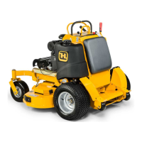
Control Panel
A. Deck clutch switch (Figure 3-1) — this switch engages
the deck. Pull the switch up to engage and push the
switch down to disengage the clutch.
For additional clutch information refer to the Mower
Deck Operation section of this manual.
B. Ignition switch (Figure 3-1) — a three position switch:
“OFF”, “RUN”, and “START”. With key inserted, rotate it
clockwise to the “START” position; release the key
when the engine starts, and the switch will
automatically return to the “RUN” position.
C. Throttle control (Figure 3-1) — a cable is linked to the
engine throttle for controlling engine speed. Move the
lever forward to increase engine rpm, move the lever
rearward to decrease engine rpm.
D. Choke control (Figure 3-1) — a cable is linked to
manually operate the engine choke. When the knob is
in the down position, the choke is in the “OFF” (run)
position. When the knob is pulled up, the choke is in
the “ON” (start) position. Do not operate the machine in
the “ON” (start) position.
E. Electronic hour meter (Figure 3-1) — registers 1/10
hour increments up to 9,999.9 total hours. It is
connected to the ignition switch. It records the
accumulative time while the ignition key is switched to
the “RUN” position.
F. Oil pressure light (Figure 3-1) — this light comes on
when the ignition switch is placed in the “RUN”
position and stays lit until the engine is running and a
safe oil pressure is developed. If the light comes on
during operation, shut the engine off immediately and
locate and correct the problem.
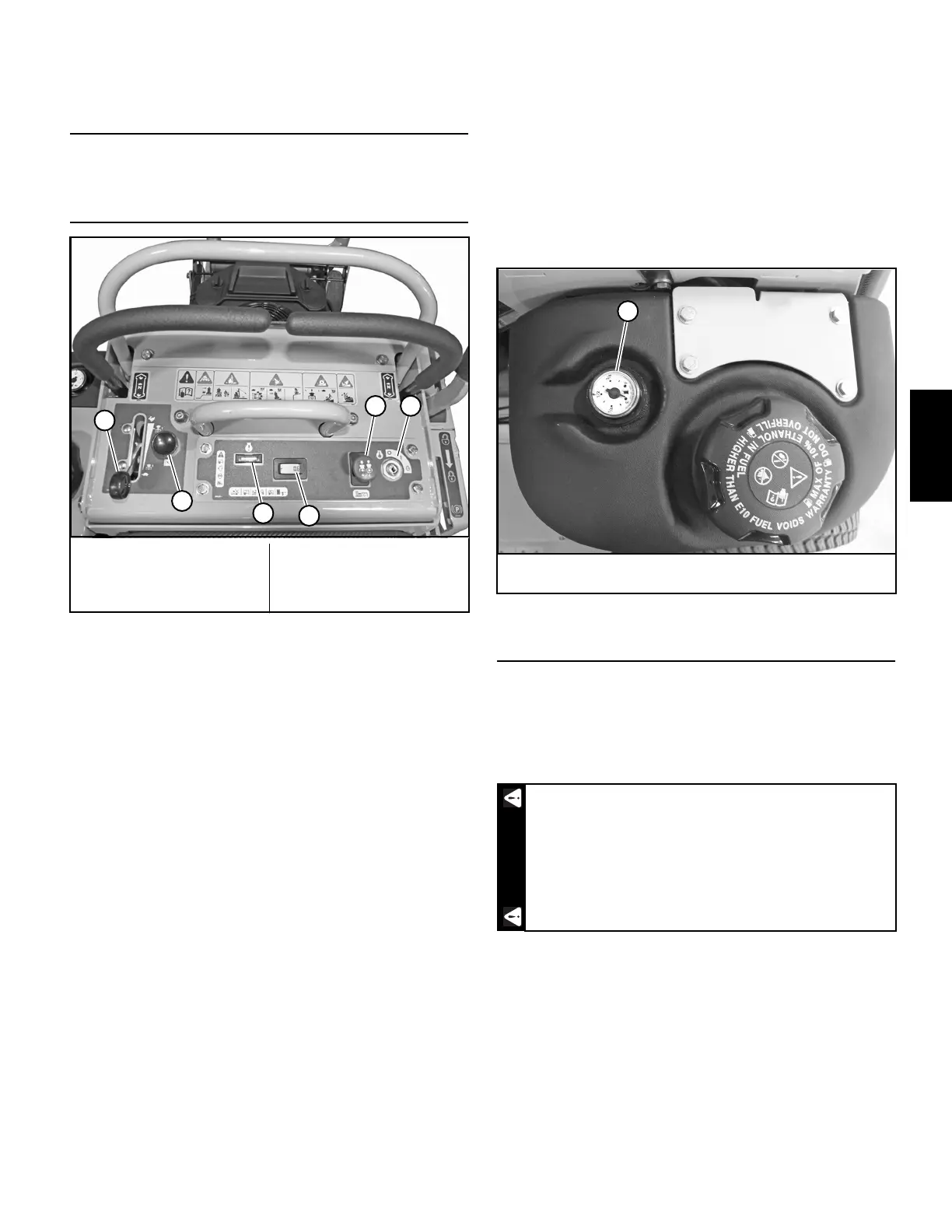
G. Fuel gauge (Figure 3-2) — This gauge shows the fuel
level in the fuel tank.
Controls
A. Steering control levers (Figure 3-3) — these levers
control the mower’s speed, direction, and stopping.
B. Park brake lever (Figure 3-4) — Push the lever back and
down to engage the park brake. Pull the lever up and
forward to release the park brake.
C. Deck height adjustment lever (Figure 3-4) — the deck
height adjustment lever is used to raise or lower the
deck. Place the deck height adjustment lever in the
transport position. Pull the adjusting pin out of the
hole that it is in and insert it into the desired cutting
height hole. Slide the deck height adjustment lever out
of the transport position and move the lever until it
rests against the adjusting pin.
Place the deck height adjustment lever in the transport
position when driving the mower from one location to
another with the blades disengaged (OFF).
A. Deck clutch switch
B. Ignition switch
C. Throttle
D. Choke
E. Hour meter
F. Oil pressure light
Figure 3-1
A
B
E
F
D
C
G. Fuel gauge
Figure 3-2
The parking brake may not hold the mower if
parked on a slope. Block or chock the machine
when parked on a slope.
G
WARNING
 Loading...