EasyManua.ls Logo

Huvitz CDR-3100 - User Manual

Huvitz CDR-3100
36 pages
Print Icon
To Next Page IconTo Next Page
Loading...
- 1 -
CDR-3100 Service Manual
`
HUVITZ Co., Ltd.

Table of Contents

Question and Answer IconNeed help?

Do you have a question about the Huvitz CDR-3100 and is the answer not in the manual?

Overview

This document is a service manual for the HUVITZ CDR-3100 refractor, providing detailed information for maintenance and troubleshooting.

Function Description

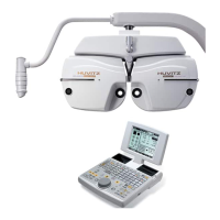
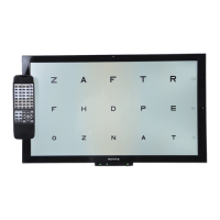
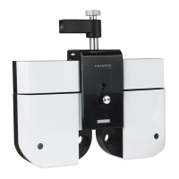
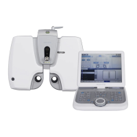
The HUVITZ CDR-3100 is a refractor designed for eye examination, specifically for measuring refractive errors. It utilizes a system of disks and gears to present various lenses and prisms to the patient's eye, allowing for precise determination of vision correction needs. The device can be controlled via an Operation Panel, which is crucial for both normal operation and service procedures like calibration.

Important Technical Specifications

The internal structure of the CDR-3100 involves multiple disk assemblies (DISK1 ASS'Y to DISK6 ASS'Y), SPH-GEAR ASS'Y, VD-MIRROR ASS'Y, and I-GEAR ASS'Y, as detailed in the "Main body (#1)" section. These components are responsible for the optical functions of the refractor.

The "Main body (#2)" section highlights sensor components: DISK1 SENSOR ASS'Y, DISK3 SENSOR ASS'Y, AUX-GEAR2 SENSOR ASS'Y, AUX-GEAR3 SENSOR ASS'Y, DISK2 SENSOR ASS'Y, DISK4 SENSOR ASS'Y, REF-PLATE ASS'Y1, REF-PLATE ASS'Y2, and DISK5 SENSOR ASS'Y. These sensors are critical for monitoring the position and movement of the various disks and gears, ensuring accurate measurements.

The "Main body (#3)" section lists the motors driving the system: DISK2 MOTOR, DISK1 MOTOR, DISK5 MOTOR, DISK4 MOTOR, DISK3 MOTOR, AUX-GEAR3 MOTOR, DISK6 MOTOR, AUX-GEAR2 MOTOR, AUX-GEAR1 MOTOR, and DISK6 SENSOR ASS'Y. These motors facilitate the precise rotation and positioning of the optical components.

The "Auxiliary gear ass'y" consists of AUX-GEAR1, I-GEAR SPACER2, I-GEAR SPACER1, I-AXIS HOLDER, I-GEAR AXIS, I-GEAR SPACER, and AUX-GEAR2. These parts contribute to the auxiliary gear mechanism.

The "SPH gear ass'y" includes SPH SHAFT TOP, SPACE WASHER, DISK1 GEAR, SPH-SHAFT, SPH-SHAFT BASE, and DISK2 GEAR, which are essential for the spherical lens adjustments.

The "REF-PLATE ass'y" comprises REF-PLATE HOLDER1, REF-PLATE HOLDER2, REF-PLATE SHAFT, and REF-PLATE, which are involved in the reference plate mechanism.

The device's power supply system, as described in the "Wiring diagram of the CDR-3100 Junction Box," supports AC 100-120V/200-240V input. The Junction Box contains an SMPS (Switched-Mode Power Supply) that outputs DC 18V for motors, DC 5V for all digital circuitry, and DC 7V for the thermal printer. It also includes fuses for protection.

Communication within the device relies on CAN (Controller Area Network) boards. The "CAN board (interior type)" and "CAN board (exterior type)" diagrams show connections for CANH, CANL, 5V, RX, NC, and GND, with a DC 9V power input for the exterior board. The communication port supports CANH and CANL signals. The manual specifies that CAN communication uses only 2 wires, the main line can reach up to 100m, and the sub line is limited to 3m. A terminator must be placed at the ends of the main line, and only one terminator is needed if there is only one system on the CAN.

Usage Features

The CDR-3100 is designed for precise refractive error measurement. The "2.2 Simplified procedures for the 2nd QC check" section outlines the steps for aging tests and post-aging test procedures. These include checking PD adjustment, convergence function, initialization sequences, and auxiliary lenses. The device allows for adjustment of PD (pupillary distance) and convergence, and the selection of auxiliary lenses. The operation panel provides a user interface for these functions, with specific key sequences for various adjustments.

The "2.3 Recommended system configuration for QC check" illustrates how multiple Refractor Bodies can be connected in a daisy-chain configuration for QC checks, with a maximum length of 500m. An Operation Panel (QCs version) and Junction Box are used in this setup.

Maintenance Features

The service manual provides comprehensive instructions for maintenance, including disassembling procedures, parts descriptions, replacement procedures, and troubleshooting.

Disassembly and Assembly:

  • Removing the main body cover: Involves unscrewing M3 screws from the Rear Cover Ass'y R (or Front cover Ass'y L).
  • Description of parts: Detailed diagrams and tables identify components within the main body, including various disk assemblies, sensors, and motors.
  • Replacement procedure for PI sensor: This involves removing the covers of the main body, disconnecting the sensor connector, and unscrewing the sensor. A critical step is to draw lines on the metal frame to mark the sensor board's original position for accurate replacement. After replacement, a "Motor Calibration" procedure is required to align the lens disks concentrically. The manual distinguishes between "Non-Concentric (bad)" and "Concentric (good)" alignment, emphasizing the importance of proper alignment for accurate measurements.
  • Removing the covers of the upper part of the main body: Illustrated with an exploded view.
  • Limit switches and motors in the upper part of the main body: Shows the locations of the PD limit switch, tilting motor, tilting limit switch, and PD control motor.
  • Disassembling the CAN boards in the main body: Requires removing a knob first.
  • Disassembling the Converter Box: Involves pulling open a section and reveals the 4-pin port and external power inlet.
  • Disassembling the Junction Box: Provides access to the voltage setting switch, power inlet, fuse holder, 4-pin CAN ports, 6-pin CAN port, and 8-pin CAN & power port for the Main Body.

Lens Cleaning:

  • A specific procedure for cleaning lenses is provided, involving turning off the instrument, removing covers, turning on the instrument, executing a lens-cleaning mode via a key sequence (ALT + MENU, ALT + START, ALT + OPEN/CLOSE), selecting the lens to be cleaned, wiping with an alcohol swab, turning off the power, and recovering the covers.

Troubleshooting:

  • Power Supply Issues: The manual details how to troubleshoot problems related to the power supply, particularly if the refractor body does not start up. This involves checking wall outlet connections, voltage settings, and fuses (U2, U3). If fuses burn repeatedly, a short circuit in the Junction Box PCB should be investigated.
  • Disk Rotation Issues: If all disks are rotating with abnormal noise during initialization, it may indicate a fault in the power supply (18V for stepping motors). Checking the U3 fuse and 18V output from the PCB is recommended.
  • PI Sensor Problems: If any of the disks are slightly off-position and come in the same position every time after initialization, or if a disk stops at a random position, or rotates more than 10 cycles, or if the axis/prism is suspected off-axis, it points to a defective PI sensor. Troubleshooting involves cleaning the sensor PCB, checking the cable and connector of the limit switch, and replacing the sensor if necessary.
  • CAN Communication Problems: If all devices on the CAN do not work, or only one device has problems, it indicates a CAN communication issue. Troubleshooting involves checking for terminator presence, short circuits (CANH and CANL), open circuits, and swapped CANH/CANL lines. The manual also provides steps for making a terminator and measuring resistance.
  • Refractor Not Responding: If one side of the refractor doesn't respond to the operation panel or the host computer after initialization, checking the CAN board (green and red LEDs) is recommended. Further steps involve checking voltage differences between CANH/CANL and ground, and using a multimeter to check continuity. If communication is not working, exchanging CAN PCBs and checking for loose/cut cables between Motor PCB and CAN PCB are suggested.

Calibration:

  • Motor calibration for the refractor body: This is a specialized procedure for aligning disk plates concentrically, to be performed only by trained and certified Huvitz personnel. It involves entering a "Calibration Mode" via a specific key sequence (ALT + MENU, ALT + START, ALT + turning dial). The user interface displays disk number, motor information, and offset counter. The manual also describes how to cancel calibration, reset the power, and check the disk position.

The manual emphasizes that modifications without prior notice for improvement are possible, and in case of instrument repair, product and problem status information (serial number, product version, OS details, symptom) should be provided to HUVITZ.

Huvitz CDR-3100 Specifications

General IconGeneral
BrandHuvitz
ModelCDR-3100
CategoryMedical Equipment
LanguageEnglish

Related product manuals