STE2
17
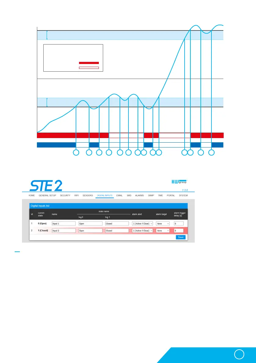
Sensor List section*
• ID – Indication of the input variable within the device.
• Current State – List of current input state (“0 (Off)” / “1 (On)”).
• Name – Input name in 12 characters (e.g. “2F left door”, “smoke section 1”).
• Alarm Alert – Definition of Alarm state for each input.
• Alarm Target – Specifies the targets for alarm alerts (SMS + E-mail). Target recipients are defined
at the Alarms tab. The drop-down menu allows selecting an existing set of targets or creating
a new one.
• Active if Close – Alarm active if the input is in state 1 (On).
• Active if Open – Alarm active in input is in state 0 (Off).
• Disabled – Input does not have a defined Alarm state.
• Alarm Trigger Delay [s] – Delays the alarm start alert by a specified time.
* DI inputs in Alarm state are highlighted.
Digital Inputs tab
WWW interface
Hysteresis
Hysteresis
1 2 3 4 5 6 7 8 9 10 11 12 13 14
Legend
Temperature range: -15 .. +25 °C
Hysteresis: 5 °C
Alarm ON
Alarm OFF
25
T[°C]
t[s]
20
15
10
5
0
0
-5
-10
-15
-20
-25
Alarm
state
Hysteresis = 5 °C
None Hysteresis