HW group
32
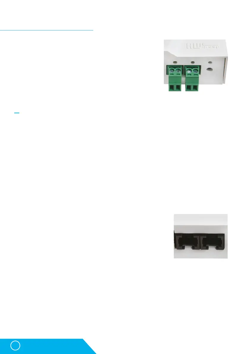
Supported interfaces
Dry contact Inputs
Dry contacts can be connected to the brackets.
For instance door contacts.
The inputs are galvanically connected to the power supply.
• Unconnected input has a value of „0(Off)“.
• Active input is identified as „1(On)“, Ohmic resistance of the
input against the Common bracket must range between 0 Ω
and 500 Ω.
Connection parameters:
• Maximum cable length: 50 metres.
• Supported sensors: Any dry contact.
• Alarm setting for each DI input
• Alarm inactive.
• Alarm state when the contact is activated or deactivated.
• Alarm state when the contact is deactivated.
• Options for reacting to Alarm state: Common settings for all inputs.
• No reaction.
• Notify of Alarm by sending e-mail or SMS.
• Reading period: 800 ms.
• Range of ID sensors: Inputs use address ID in the range of 1 to 9.
• Sensor name: The sensor can be named independently with up to 12 characters.
• Sensor disconnection detection: No, the disconnected sensor returns to the value „0(Off)“.
RJ11 – 1-Wire bus
Digital bus by Dallas Semiconductor, each sensor has a unique ID.
We recommend lines up to a total length of 60 m. There are known
cases of experimentation with bus function up to a distance of
tens to hundreds of metres.
Flawless functioning cannot be guarantee for cables lines than
60 m from one connector on the device. It depends on the make
of the cable, topology of the line and environment where the line is installed.
STE2 – User Manual