3.3
5. The V-25APC blade is only exposed to the operator at the cutting area. A blade guard protects the operator from
the blade between the drive wheel assembly and the actual cutting area. A black knob on the cover allows it to be
swung open.
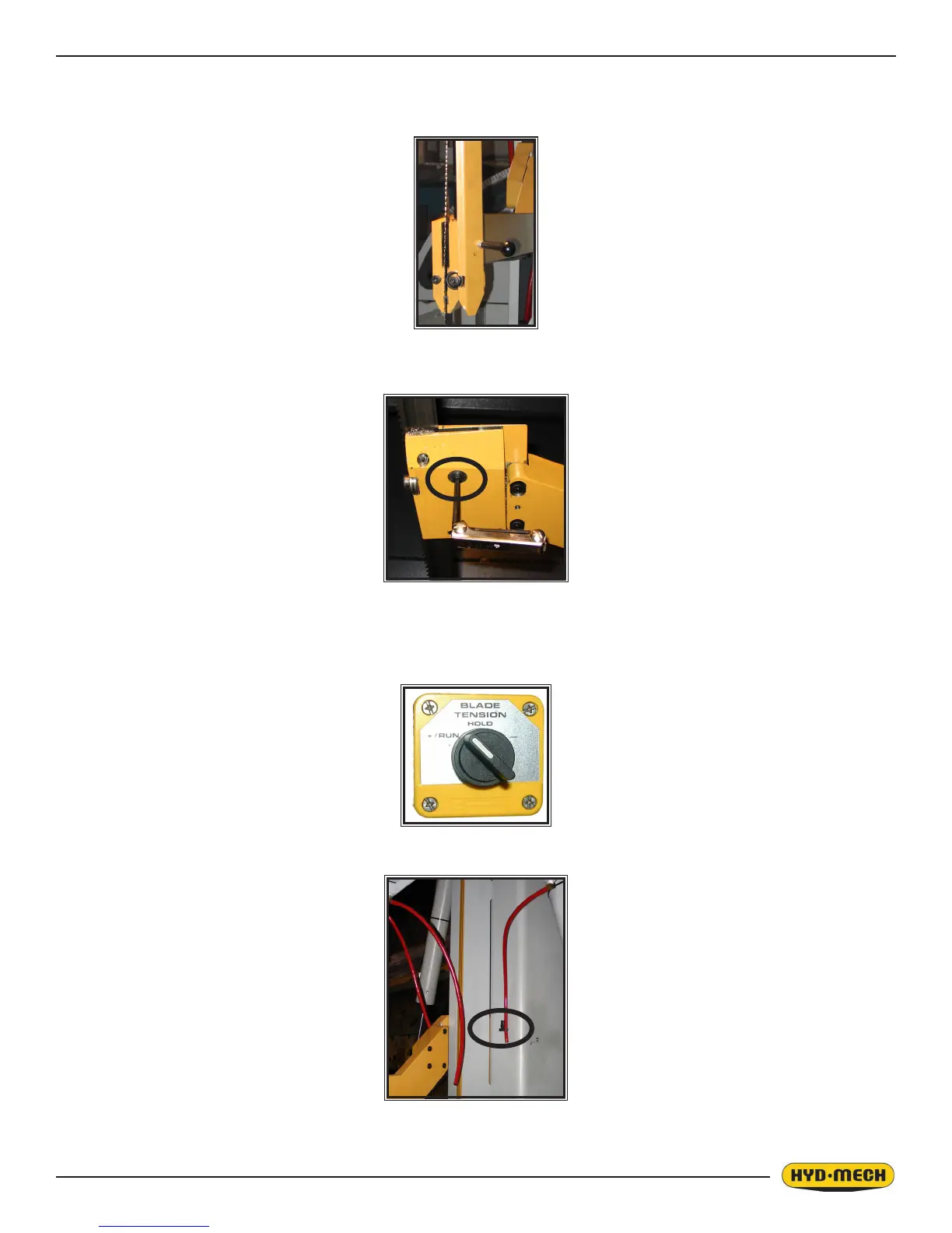
6. It is necessary to release the carbides on both guide arms from the locked position so that the blade can be easily
removed. As shown in the photo the carbides are released by loosening the socket head cap screw with a 5mm
allen key (2 turns CCW).
7. Turn the Blade Tension Switch from the TIGHTEN position “ + RUN”, through the unmarked, central HOLD posi-
tion, and briey to the LOOSEN position “ - “.
• By jogging the switch between hold and loosen, it is possible to regulate the degree of looseness of
the blade. It is helpful to have the blade just loose enough that it stays on the wheels and in the blade
guides, but can be manually pulled off the wheels and out of the guides.
8. Pull the blade forward off of the blade wheels and out of blade guides.
9. The door drain tube must be released from its retainer in order to remove the blade.
10. Store or dispose of the used blade.
 Loading...