3.6
DRIVE WHEEL ADJUSTMENT
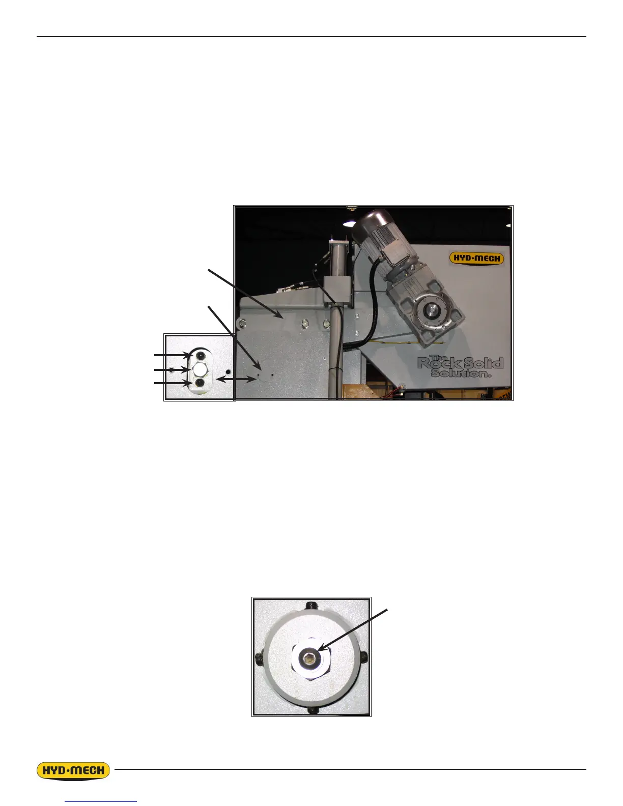
Adjustments should be made with the blade tension released slightly. The drive wheel assembly is mounted on the drive
arm weldment which has two set screws and a hex bolt in a “push/pull” arrangement. Gain access to these adjusters by
removing the cover plate on the head upper side cover. To make adjustments, loosen bolt “A” and back one of the set
screws “B” out several turns, so that adjustment is made with just the other set screw and the hex bolt. Use the hex bolt to
pull the adjustment arm in and cause the blade to track with less overhang. Use the set screw to push the adjustment arm
out and cause the blade to track with more overhang. Check the blade movement after each 1/4 turn of set screw “B” by
running the blade at minimum speed for a couple of rotations. When the tracking is within specication, tighten the other
set screw “B” to contact the surface of the head post weldment, then tighten bolt “A”.
Drive Arm Weldment
Cover Plate
B
A
B
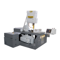
IDLER WHEEL ADJUSTMENT
Before adjusting the idler wheel, reduce blade tension and slightly loosen the button head cap screw “D”. There are four
set screws; “A” set screws should not be adjusted as they are pivot points. Set screws “B & C” are adjusted by turning one
out and the other in a 1/4 turn, and then tightening the rst again. Check the blade movement after each 1/4 turn adjust-
ment by running the blade at minimum speed for a couple of rotations. Loosening “C” and tightening “B” will push the
blade off the wheel. Loosening “B” and tightening “C” will pull the blade onto the wheel. When correct tracking is achieved,
re-tighten “D”.
A
C
B
A
D