v - Titan 625 Owner’s Manual
Figure 7-1. Electrical Schematic ..................................................................................7-2
Figure 7-2. Wiring Diagram - View 1 of 2 .....................................................................7-3
Figure 7-3. Wiring Diagram - View 2 of 2 .....................................................................7-4
Figure 9-1. Adhesive/ Material Reference .................................................................... 9-2
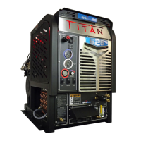
Figure 9-2. Titan 625 with 100 gallon URT ................................................................... 9-3
Figure 9-3. Titan 625 with 70 gallon URT ..................................................................... 9-5
Figure 9-4. Console Assembly - View 1 of 5 ................................................................9-7
Figure 9-5. Console Assembly - View 2 of 5 ................................................................9-8
Figure 9-6. Console Assembly - View 3 of 5 ................................................................9-9
Figure 9-7. Console Assembly - View 4 of 5 ..............................................................9-10
Figure 9-8. Console Assembly - View 5 of 5 .............................................................. 9-11
Figure 9-9. Blower Assembly ....................................................................................9-13
Figure 9-10. Blower Heat Exchanger Assembly .........................................................9-15
Figure 9-11. Engine Assembly - View 1 of 2 ...............................................................9-17
Figure 9-12. Engine Assembly - View 2 of 2 ..............................................................9-18
Figure 9-13. Exhaust Assembly .................................................................................9-20
Figure 9-14. Flywheel Plate Assembly .......................................................................9-21
Figure 9-15. Frame Assembly ....................................................................................9-23
Figure 9-16. Lower Dash Assembly - View 1 of 2 ......................................................9-25
Figure 9-17. Lower Dash Assembly - View 2 of 2 ......................................................9-26
Figure 9-18. By-Pass Valve Assembly - View 1 of 2 ..................................................9-28
Figure 9-19. By-Pass Valve Assembly - View 2 of 2 ..................................................9-29
Figure 9-20. High Pressure Manifold Assembly .........................................................9-30
Figure 9-21. Dierential Check Valve Assembly ........................................................9-31
Figure 9-22. Orice Assembly ....................................................................................9-32
Figure 9-23. Pump and Silencer Assembly ................................................................9-33
Figure 9-24. Pump Assembly - View 1 of 2 ................................................................9-34
Figure 9-25. Pump Assembly - View 2 of 2 ................................................................9-35
Figure 9-26. Side Cover - Console Assembly ............................................................9-37
Figure 9-27. Temperature Control Assembly ..............................................................9-39
Figure 9-28. Top Cover Assembly ..............................................................................9-40
Figure 9-29. Upper Dash Assembly ...........................................................................9-41
Figure 9-30. Water Box Assembly .............................................................................. 9-43
Figure 9-31. Diuser Filter Assembly .........................................................................9-45
Figure 9-32. Chemical Jug Tray/Hose/Connection Package Assembly .....................9-46
Figure 9-33. Chemical Jug Tray Assembly .................................................................9-47
Figure 9-34. 100 Gallon Universal Recovery Tank (URT) Assembly ..........................9-48
Figure 9-35. 100 Gallon Universal Recovery Tank (URT) Cover Assembly ...............9-50
Figure 9-36. 70 Gallon Universal Recovery Tank(URT) Assembly .............................9-52
Figure 9-37. 70 Gallon Universal Recovery Tank (URT) Cover Assembly .................9-54
Figure 9-38. Vacuum Relief Valve Assembly ..............................................................9-56
Figure 9-39. Vacuum Inlet Stopper Assembly ............................................................9-57
 Loading...