Power supply
(positive at contacts 1)
(negative at contacts 2)
Max power consumption 50 W
Current supplied to solenoid Imax= 3.3A square wave PWM type; (for ex-proof valves Imax = 2,5A)
Nominal reference signal, factory preset E-RP-AC-01F: : 0 +5V at contact 10 (GND on 11)
E-RP-AC-05F: : ± 5V at contact 10 (GND on 11)
4-20 mA for /I at contacts 10 (+) and 11 (-)
Reference signal variation range,
(scale adjustment)
Input signal impedence Voltage Ri > 50 KOhm - (/I option Ri = 316 Ohm)
Potentiometers supply +5V / 50 mA at contact 8 and -5V / 10mA at contact 9
Ramp time 5 or 90 sec. max (0 ÷100% of reference signal) see
쪮
Enabling signal V = 5 ÷ 24V
DC
on contact 7
Electrical wiring Coil: 2 x 1 mm
2
to 20 m 2 x 1,5 mm
2
shielded to 40 m
Card format Sealed box IP 65
Connections 14 contacts - terminal strip
Cable Clamp Dimension PG7 - water proof - Cable Ø 5 ÷ 6,5
Operating temperature 0 ÷ 50 °C (storage -20 ÷ +70 °C)
Box dimensions 175 x 80 x 57 mm
Weight 940 gr.
Features Rapid solenoid excitation and switching off
Outputs to solenoids protected against accidental short circuits.
3 MAIN CHARACTERISTICS OF E-RP-AC ELECTRONIC DRIVERS
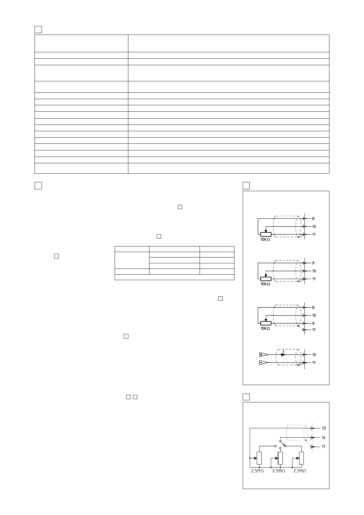
5 EXTERNAL REFERENCE SIGNALS
EXTERNAL CONNECTIONS
POTENTIOMETERS
EXTERNAL REFERENCE
GENERATOR AND /I OPTION
SOLENOIDS S1 AND S2
REFERENCE
SOLENOID S2
REFERENCE
SOLENOID S1
REFERENCE
Stabilized : 24VDC (12 VDC ± 10% for 12 DC option)
Rectified & filtered : V
RMS = 21 ÷ 33 (max ripple = 2Vpp)
± 10V max ± 2,5 V min
4 GENERAL SPECIFICATIONS
4.1 Power supply and wirings
The power supply must be appropriately stabilized or rectified and filtered. If the power supply is
generated by a single phase rectifier, use a 10000µF/40V capacitor; if pulse voltage is generated
by a three phase rectifier connect a 4700µF/40V capacitor (see table ).
Connect the reference signal to the main electronic control by means of shielded and twisted
cables. Pay attention: the negative and the positive poles must not be exchanged each other.
Shield the wirings to avoid electromagnetic noise (EMC).
It is suitable to keep the driver and its cables far from any electromagnetic radiation source (like
cables where high currents flow, electric motors, transformers, relays, solenoids, portable radio-
transmitter, etc.). Wire the earth connection as shown in , according to CEI EN 60204-1 stan-
dards.
Connect the shield of the driver
to the noiseless earth terminal
(TE) .
The driver is designed to correc-
tly work with 24 V
DC
(±20%) or 12
V
DC
(±20%) nominal voltage sup-
ply coupled with coils having a
resistance from 2,0 Ω to 13,4 Ω,
as shown in the side table.
4.2 Reference signal
The electronic driver is designed to receive voltage or current reference signals, see table
Note that drivers suitable to receive current reference (option /I) have signal values in the range 4
to 20mA.
It is possible to use current option also for double channels drivers type E-RP-AC-05F using the
reference inversion signal on contact 12.
4.3 Monitor signal
This voltage output signal allows to measure the current supplied to the coil, read by a voltmeter
between the test points on the card (see ).
Reading scale is 1 mV = 1 mA. To visualize the signals use voltmeters with impedance >10 K
Ω
.
4.4 Set code
Basic calibration of the electronic driver is factory pre-set according to proportional valve it has to
be coupled with. These pre-calibrations are identified by a standard number in the model code as
follows:
1 = RZGO, KZGO 2 = RZMO, AG*ZO, LI*ZO
3 = DHZO, DKZOR 4 = DPZO-A-*5, DPZO-A-*7
6 = QV*ZO(R), LIQZO
For ex-proof valves, insert an “A” before the code of adjustment.
For example, the code of adjustment for RZGA is A1 (see table E120).
4.5 Calibrations accessible to the user, see
, .
Scale
The relation between driving current and reference signal can be regulated with the Scale adju-
sment. For single solenoid valves with two external operating positions, the reference signal is the
same as the double solenoid driver. Separate Scale potentiometer for solenoid S1 and S2 enable
the electronic driver to be set for different output currents, obtaining differential hydraulic opera-
tions.
Bias (dead band)
Regulation of dead band adjusts the hydraulic zero of the valve (adjustment of starting position) to
the corresponding electrical zero. The electronic driver is factory preset for the valve it is coupled
according to the set code (see section 4.4). For double solenoid driver E-RP-AC-05F/* a step func-
tion generator becomes active at an input reference voltage signal greater than ± 100 mV ena-
bling start current set by Bias potentiometers S1 and S2 for indipendent solenoid Dead Band regu-
lation.
9
13
11
11
5
98
Nominal supply Valve code
R at 20 °C [Ω]
24 VDC
*ZMO, *ZGO, *ZO(R)-A-* (1)
3,2
*ZMA, *ZGA, *ZO(R)-A-* (1)
3,2
*ZMO, *ZGO, *ZO(R)-A-*/18 13,4
12 VDC *ZMO, *ZGO, *ZO(R)-A-*/6 2,1
(1) Standard coupling
6 EXTERNAL RAMPS - /RRE option
EXAMPLE WITH THREE EXTERNAL RAMPS