G100
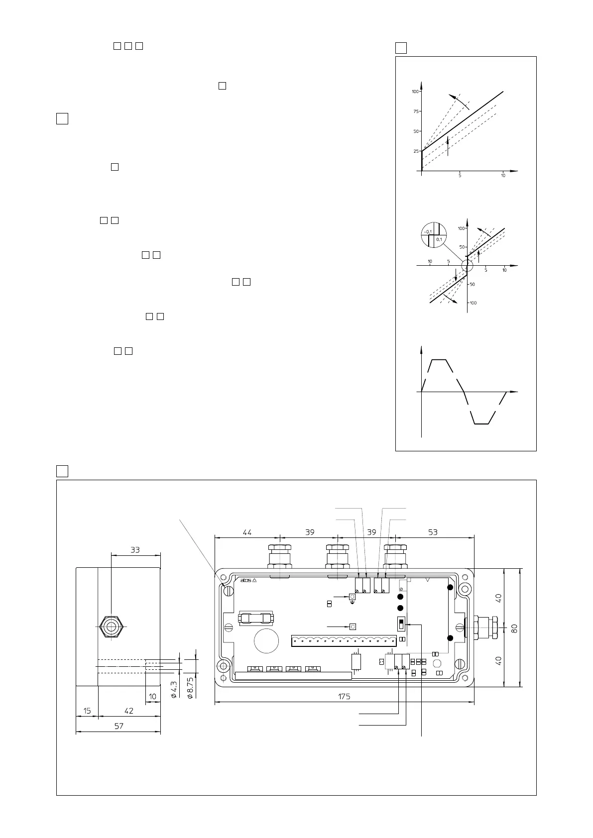
9 E-RP-AC-05F TOPOGRAPHICAL VIEW OF REGULATIONS AND DIMENSIONS [mm]
8 RAMP AND SETTINGS
E-RP-AC-01F ADJUSTMENT
Current [%]
Scale
adjustment
Bias adjustment
Reference [V]
Reference [V]
Bias S1
Scale adjustment
Bias S2
Scale
adjustment
Current [%]
Valve opening
/RR OPTION - UP AND DOWN RAMPS
P1 P2
P1 P2
E-RP-AC-05F ADJUSTMENT
7 INSTALLATION AND START-UP
It is advisable to perform calibration procedures in the order given below.
7.1 Warning
– Never insert or remove the driver connector while the electronic system is powered on.
– Voltages must always be measured with reference to GND (connector contact 11) or test point.
– Refer to to identify components mentioned in calibration procedures.
7.2 Start-up
Factory preset adjustments may not meet the desired requirements for the specific application and
performances can be optimized by on-site re-adjustements of bias, scale and ramps potentiome-
ters, in sequence.
– Connect the electronic driver according to the desired connection diagram
(see
,
)
– The current supplied to the coil can be measured by a voltmeter connected between test point
(current monitor and GND)
For E-RP-AC-05F the drive enabled led (S1 or S2) shows the supplied coil.
Enabling signal, see
, .
The electronic driver operate when the contact 7 is supplied with an enabling signal (usually 24 V
DC
).
It could be useful in emergency conditions to inhibit the driver by zeroing this signal
Bias adjustment (Dead band compensation), see
, .
– Supply a reference signal voltage (0V
DC
for E-RP-AC-01F and ±0,1 V
DC
for E-RP-AC-05F).
– Gradually turn bias potentiometer(s) until a movement of the controlled actuator is obtained.
– Turn in the opposite direction, until the actuator is stopped.
Scale adjustment see
, .
Supply max reference signal voltage (for E-RP-AC-05F driver repeat for max negative voltage) in
the specificated range and turn scale potentiometer(s) until the actuator speed reaches the desi-
red value.
Ramps (see
,
).
– Turning ramp potentiometer(s) clockwise acceleration(s) and deceleration(s) can be reduced
to obtain optimization of the complete system.
12
98
98
98
1211
11
9
Time
Deadband compensation solenoid S1 P4
Scale adjust for solenoid S1 P3
Acceleration and deceleration ramp P1
Deceleration ramp (option /RR only) P2
Maximum ramp time selection SW1
- with SW1 in position 1 max ramp time is 5 seconds
- with SW1 in position 2 max ramp time is 90 seconds
Current monitor point
(mV read = mA)
Test point GND
P3 P4 P5 P6
GND
OUT (I = V)
FUSE 4A RVF
P5
* Scale adjust for solenoid S2
P6
* Deadband compensation solenoid S2
* only for E-RP-AC-05F/*
Earth connection
(cable shield)
P1 P2
SW1
1
2
Ramps, see
, , .
The internal ramp generator circuit converts a step input signal into a slowly increasing output
signal (solenoid current) .
The rise/fall time of the current is set via potentiometer P1, to a maximum time of 5 or 90 sec (swit-
ch SW1) for 0 - 100% of reference signal. The option /RR provides dissymetrical ramps, (P2) /RRE
allows external ramp setting as shown in table .
To switch off the ramp circuit connect contacts 13 and 14 on the electric connector.
986
6