© 2016 www.hysecurity.com SlideDriver Installation and Assembly MX3629-01 Rev. B Page 6
Assemble, Align & Install Drive Rail
Drawings NOT to Scale
2
1
Connect sections of the drive rail.
Use roll pins to join the sections of the drive rail. To prevent the pins
from moving during assembly, crimp the pin channels with a pliers.
Secure the toggle handle.
Disengage the drive wheels by pulling on the toggle handle.
Wire the toggle handle clamp open so the wheel doesn't fall closed
when you insert the drive rail through the chassis
WARNING
Be careful where you place your hands and ngers when you disengage the
drive wheels. The compression spring at the base of the clamp causes the
handle to drop suddenly which can cause serious injury.
Standard grooved
drive rail
Optional anged drive rail used for
solenoid lock applications.
AdvanceDrive™
and XtremeDrive™
wheels shown.
Use wire to secure
the toggle handle so
the clamp remains
open and the drive
wheel doesn't fall
closed while you
insert the drive rail.
Drive rail
Limit ramp
Limit switch (interior of chassis)
CAUTION
When sliding the drive rail through the cut out in the
chassis, DO NOT damage the limit switches. Damage
to the limit switches during installation is not covered
by the Warranty.
U bolt securing the
drive rail.
Compression spring controls
drive wheel gripping force
Clamped
Unclamped
Handle Position
3
Clamp Drive Rail to Gate
Identify the gate structure nearest the operator and
temporarily clamp the drive rail onto the gate.
4
Set a String Line, Align Drive Rail and Insert Shims,
if needed.
For reference, run a string line along the entire length of the
drive rail. Compare the edge of the drive rail with the string
line. Place shims between the upright support structure and
drive rail to keep the drive rail straight and level.
String line
Gate edge
Limit ramp
SlideDriver
U bolts fasten drive
rail to support posts
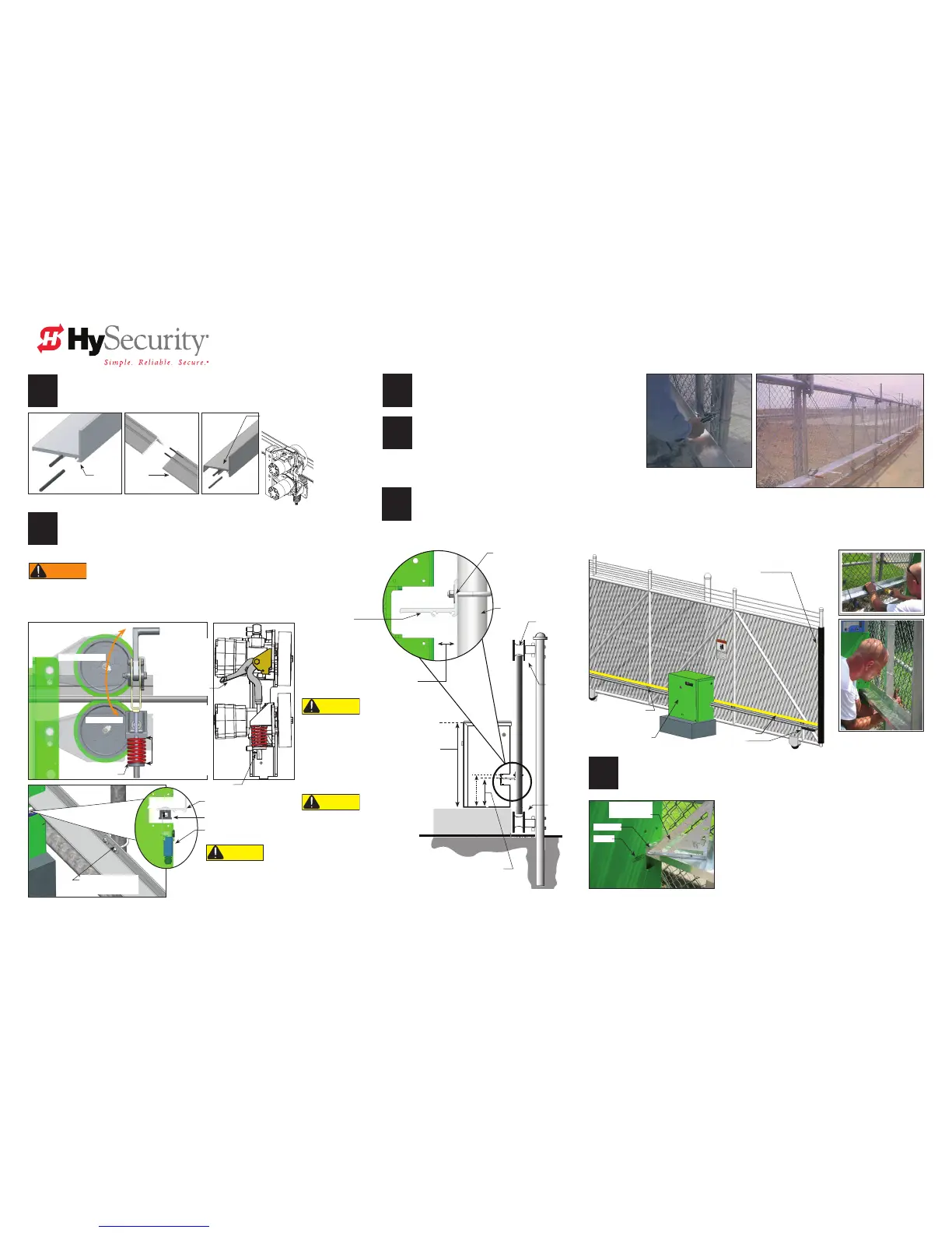
5
Align and Secure Drive Rail
Align the top of the drive rail with the label on each side of the operator's chassis. If necessary, loosen the C-clamps and move the
drive rail up or down along the length of the gate. Drill holes through the drive rail ange and insert U bolts from the far side.
Install U bolts along the upright support structure, as needed. HySecurity recommends that you attach to a minimum of 3 supports per
length of drive rail. Keep drive rail spans straight and level. Distance between attachment points should be less than 10 feet (3 m).
Remove the C clamps when the drive rail is fully secure.
Manually, open and close the gate.
Check and adjust the height of the drive rail.
Label
Drive rail
Triangle tool
rafter square
NOTE: DO NOT use through bolts or self-
tapping screws because you won't be able to
adjust the drive rail at a later date.
6
Install additional U bolts, as necessary.
NOTE: Make sure the drive wheel will be centered on the drive rail
when placed under load.
With the drive rail secure, tighten the chassis
anchor bolts.
NOTE: Over its entire length, the drive rail must
be level and aligned with the label on the chassis to
within ± ¼-inch (6 mm).
When clamped, the
red spring should
be compressed to
a height of 2-inches
(5 cm). Adjust the
nut at the base of
the spring to set the
proper tension.
Nut adjusts tension
CAUTION
When drive rail and limit
ramps (see page 5) are
installed, the drive rail must
be aligned and the operator's
chassis secure before clamping
the drive wheels and adjusting
the compression spring.
CAUTION
CONCRETE PAD
Grooved drive rail
NOTE: Drill holes to increase
traction where drive wheels
rst engage the drive rail.
Other traction considerations:
HySecurity XtremeDrive™
Wheel System
Gate face*
Use shims as needed.
*NOTE: The best material to
use for shims is non-corrosive
materials, such as aluminum or
heavy-duty plastic.
Support post
Wheel cover
Height from top of drive rail to bottom of
gate operator. All models: 9¼” (23.5 cm)
NOTE: if using XtremeDrive™ wheels
mount drive rail ¼” to ½” (6 to 13 mm)
higher.
All models
(except SD 200):
26” (66 cm)
SlideDriver 200:
33½” (85 cm)
Distance: 1½" (38 mm)
Wheel cover
Roller guide and
bracket support
All models: 9¼” (23.5 cm)
Exceptions: SD 80 & SD 200
using XtremeDrive™ wheels,
9½” to 9¾” (23.5 to 25 cm)
XtremeDrive™

 Loading...


