© 2016 www.hysecurity.com SlideDriver Installation and Assembly MX3629-01 Rev. B Page 5
Set up and Assembly
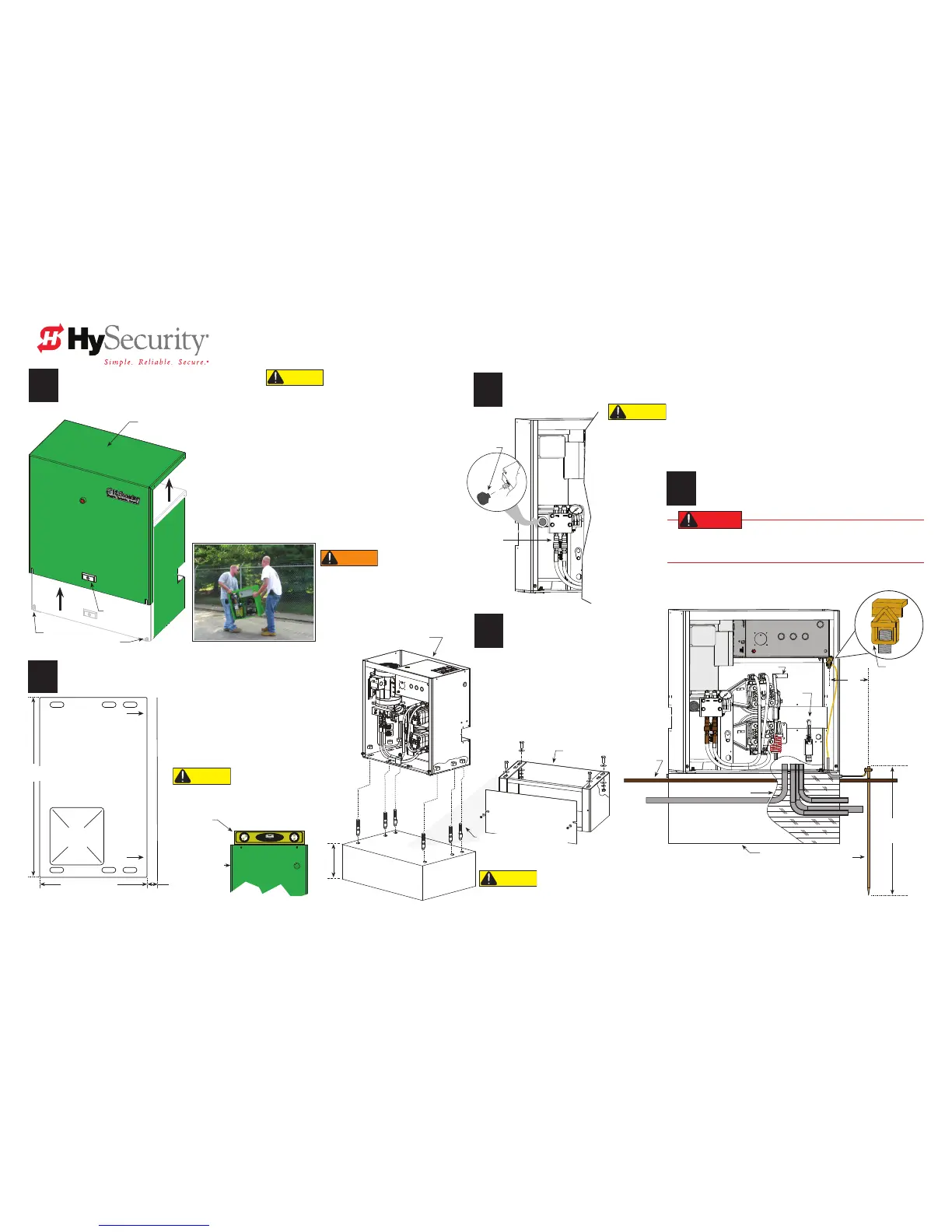
unpaCk tHe slidedriver
Phillips head screws
Loosen, DO NOT remove.
Drawings NOT to Scale
1. Loosen two Phillips head screws.
NOTE: Leave sufcient overhead clearance to remove cover and open the
control box.
2. Remove the cover by tilting it slightly toward you while lifting it
up off the top of the operator.
NOTE: Use the supplied keys to release the lock if your model includes that
option.
3. Remove the foam pieces around the motor and the red spring.
4. Remove the ship with kit plastic bag.
replaCe tHe vent plug
WARNING
Obtain help before lifting or moving the
operator. SlideDriver models can weigh over
260 lbs (118 kg). Failure to comply may result
in serious injury to personnel, damage to the
equipment, or both.
1
2
3
1. Align the operator. Locate rear panel
1½-inch from the face of vertical uprights.
2. Install concrete anchors (½ x 4-inch
minimum)
3. Tighten the nuts, but leave room for
adjustments.
4. Level the operator. Shim with plastic or
aluminum to prevent corrosion.
Mark tHe anCHOr bOlt lOCatiOns
CAUTION
Replace the vent plug with the breather cap before operating the SlideDriver.
Air pressure vents through the cap instead of through the pump seal and helps
prevent rust by allowing
condensation to evaporate. If you do not replace the vent
plug with the breather cap, you will void the Limited Warranty.
After you remove the operator, cut out the
anchor bolt template on the side of the
SlideDriver box.
Use the template to mark the location of the
anchor bolts that will secure the SlideDriver to
the concrete pad.
CAUTION
Review the dimensions on page 1. Proper alignment of
the SlideDriver operator and its drive rail is critical.
FACE OF GATE FACE OF GATE
CONDUIT
CUT-OUT
Gate
Side
-Puerta
Lado-
Gate
Side
-Puerta
Lado-
-CONDUCTO
CORTAR-
CAUTION
Do NOT fully tighten the anchor bolts until after the drive rail is installed. See page 4.
4
install tHe CHassis
install tHe eartH grOund
5
DANGER
The potential for lightning discharge exists with all gates, fences and
gate operators. National Electric Code (NEC) - Article 250 requires a
separate earth ground in addition to the required equipment ground.
The gate operator must be grounded per NEC, NFPA 780
and local building standards and codes.
CAUTION
DO NOT pick the operator up by its sides or
tip it. Hydraulic uid can leak or damage to the
chassis may occur and void the Warranty.
26-inches
(66 cm)
14½-inches (37 cm)
1½-inch
(38 mm)
Level
Optional base riser
Side view
Anchor bolts (½ x 4-inch, min.)
Minimum 4 anchor bolts
(6 bolts required for heavy
gates: 80 and 200 operators.)
Lock (optional)
Cover
Breather cap
Quick
disconnects
(QDs)
Option:
SlideDriver Base Riser (most models)
Inches: 26W x 12H x 14½D
Centimeters: 66W x 30H x 37D
Option:
SlideDriver Base Riser (200 series): Same H & D, with 47"W (109 cm)
Ground lug
Limit
switch
Toggle handle
Earth ground
Consult local
codes for
proper depth
Grade level
Cut away view
Conduit
SlideDriver chassis
Control Box
3 ft
(91 cm)
Maximum
distance
Concrete pad
Rear panel
Minimum depth 16" (41 cm)
or frost line. See local codes.
Concrete pad
conduit, not shown

 Loading...


