© 2016 www.hysecurity.com SlideDriver Installation and Assembly MX3629-01 Rev. B Page 9
Complete the Installation
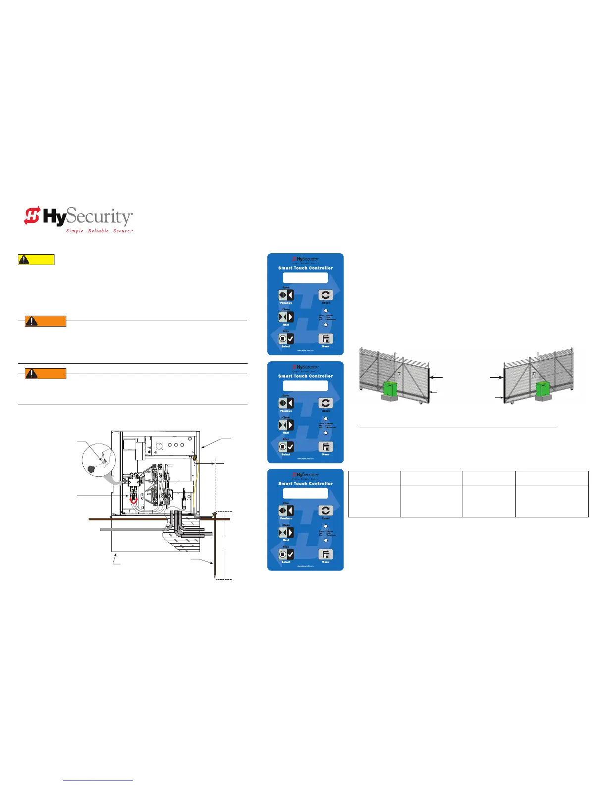
Left Handing: Swapping Hydraulic Hose Positions
Initial Setup: Menu Mode
Drawings NOT to Scale
Changing Electrical Connections in the Field
CAUTION
For in-eld conversions, the NEC requires that the voltage label on the motor be changed to match the new
conguration. Contact HySecurity for a replacement label.
To reconnect the electric motor and the 24V control transformer, refer to the motor connection
diagram found either on the motor's nameplate or inside the motor connection box. Be sure to
read the WARNINGS below if planning to convert from 1Ø to 3Ø, or vice versa. The electric motor
will need to be replaced.
SlideDriver 50VF-series and all 2 hp operators CANNOT be connected to 115/120VAC, 1Ø power or 575V, 3Ø
power. If any attempts are made to do so, serious injury and possible electrical shock may result. Any electrical
damage occurring to the operator will not be covered by the Warranty.
UC 2
USAGE CLASS
HYSECURITY
GATE STOPPED
SH R (RIGHT)
GATE HANDING
When the SlideDriver is installed, power connections made, and the operator turned ON, a setup
menu appears. The gate will not move and the controls will not function until the prompts have
been answered. The prompts include:
• Usage Class. Set the usage class to I, II, III, IV depending on the site.
Four different vehicular usage classes are dened by UL 325.
Information about the classes can be found in the safety section of the SlideDriver
Programming and Operations Manual, online through DASMA Technical Data Sheets
www.dasma.com or UL 325 gate safety standards www.ul.com
• Set Handing. SH 0 = gate disabled, SH L = Left hand, SH R = Right hand
Gate handing is determined by viewing the gate opening from the secure side. If the gate
opens to the left, the gate must be set for left handing.
NOTE: All SlideDrivers are set at the factory for right handing. If the gate has left handing, you
must swap the position of the hydraulic hoses. See the illustration this page.
Keypad Navigation
To navigate within Menu mode, use the following chart:
Menu Mode Navigational Buttons
To edit the Menu To navigate through
the selections
To choose what is
on the display
To navigate between
menus
Press Select
Two left characters blink
indicating the display is
ready to accept a menu
change.
Press Next or Previous
Continue pressing Next to
view all selections
Press Select
Blinking characters
become static
Press Next or Previous
Advance = press Next
Previous = press Previous
For More Information
Brake valve adjustment is described on the yellow tag (MX001853) wire tied to the gate operator.
Review the SlideDriver Programming and Operations Manual, D0559 for information regarding
gate operator programming congurations, user relays, troubleshooting, safety considerations,
maintenance, and other requirements.
Replace red vent plug
with breather cap
Concrete pad
Ground rod
Consult local codes for
proper depth
Cut-away view
Grade level
SlideDriver
3 ft
(91.4cm)
Maximum
distance
Operator is shipped
hydraulically congured for
“right hand” operation.
Swap hydraulic hoses for left
handing operators.
Left hand gate
OPEN
Right hand gate
OPEN
SlideDriver viewed
from the secure side

 Loading...


