‐
RX_VCO
PLL Sky72310
Buffer
Amp T/R_Switch
RF feedback LPF
TX_VCO
Mod_1
Loop Filter
VC_TXCO
Mod_2
PN: ≤-80 (dBc/Hz)@1KHz
PN: ≤-112 (dBc/Hz)@12.5KHz
PN: ≤-120 (dBc/Hz)@25KHz
PN: ≤-136 (dBc/Hz)@100KHz
PN: ≤-145 (dBc/Hz)@1MHz
Two Point modulation:
0.1~5KHz modulate
ripple≤±0.5dB
Fc=19.2MHz
To TX
To Mixer
2SC5108
Gain≤5dB
isolation≥20dB
Current≤4mA
2SC3356
Gain≥10dB
isolation≥15dB
Current≤10mA
3dB BW≤3.5K
Phase Margin:30-55°
A=0.1Vpp~2.0Vpp
S21=-3dB
Fpass=500MHz
Fstop=800MHz
Astop=40dB
Kv≤30MHz/V
CV=0.8~4.1V
F=341.95~411.95MHz
PN≤-116dBc/Hz@12.5KHz
Kv≤30MHz/V
CV=0.8~4.1V
F=400~470MHz
PN≤-116dBc/Hz@12.5KHz
3.0v for core&Vp
Compare frequence:4.8MHz
Prescaler Level:50~250mVpp
Pi Attenuator
isolation=1dB
FGU Close Loop:
Residual noise deviation:
300~3KHz:≤50Hz
50Hz~15KHz:≤100Hz
Reverse Isolation:>40dB(Buffer to Amp)
RF_OUT: ≥0 dBm (to RX)
≥-1 dBm (to TX)
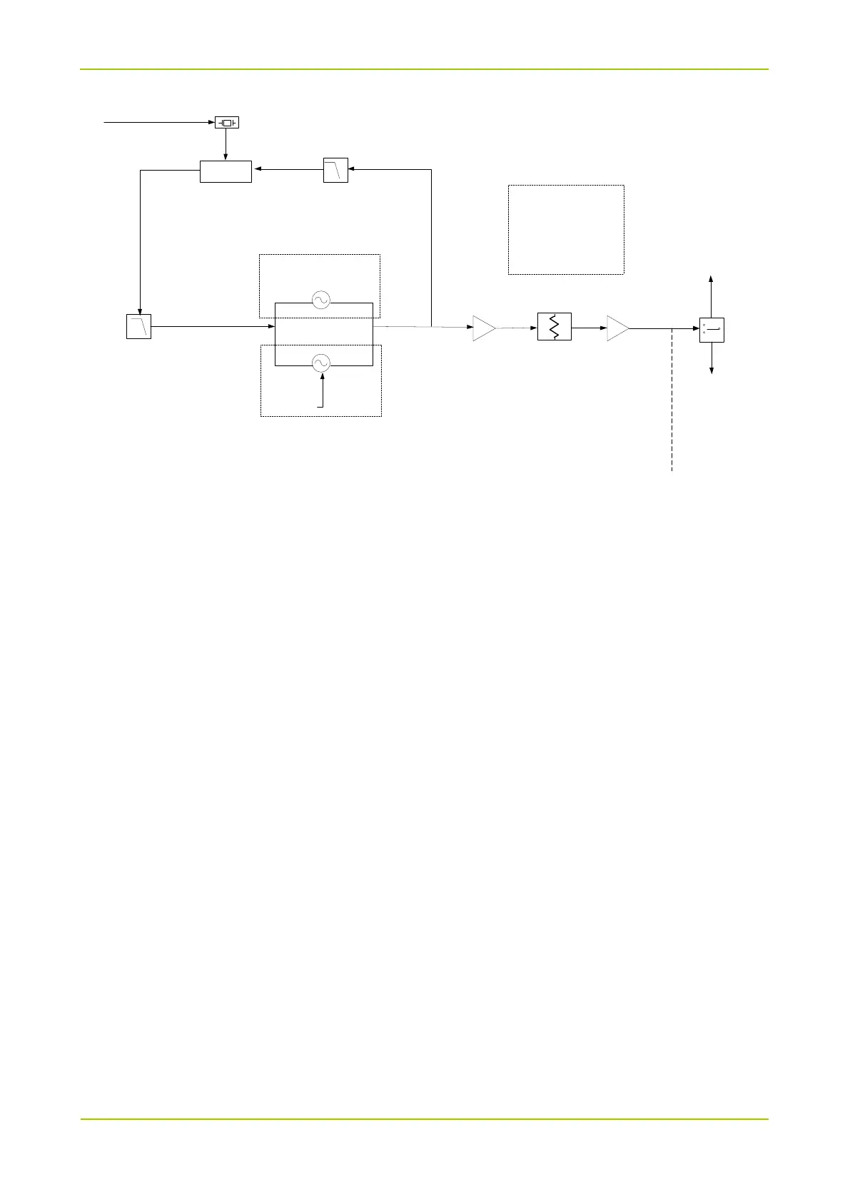
Operating Principle of PLL
The 19.2 MHz frequency generated by the reference crystal oscillator goes to the frequency divider of
PLL for frequency division. Then, the frequency divider generates the reference frequency (step
frequency f1). Meanwhile, the frequency generated by VCO goes to the frequency divider of PLL for
frequency division. Then, the frequency divider generates the frequency f2. After that, frequencies f1 and
f2 are compared in the phase detector (PD) to generate continuous pulse current. The current goes to
the loop filter for RC integration, and is then converted to control voltage (CV). Then the CV is sent to the
varactor of VCO to control and adjust the output frequency of VCO directly until the CV becomes
constant. At this time, PLL is locked. The stable frequency output by VCO goes to the TX/RX path after
passing through two buffer amplifiers.
Operating Principle of Voltage Controlled Oscillator (VCO)
VCO employs Colpitts oscillator circuit. There are two types of VCO: RX VCO and TX VCO. RX VCO
provides LO signal while TX VCO provides carrier for TX signal. When the VCO is operating, it obtains
different output frequencies by changing the varactor's CV and then uses the control signals
VCC_VCO_L and VCC_VCO_H to switch the operating status between TX and RX. VCO_L is used for
receiving while VCO_H is used for transmitting.
Two-point Modulation
In TX mode, the two-point modulation technology is employed, to obtain higher modulation accuracy and
lower 4FSK bit error rate. MOD_VCO and MOD_REF send the modulation signal to the modulation end
of VCO and the reference crystal oscillator of PLL respectively to modulate TX VCO and the reference
crystal oscillator.