Circuit Descriptions
UHF1 (400‐470 MHz)
12
5.2 RF Section
5.2.1
Transmitter Circuit
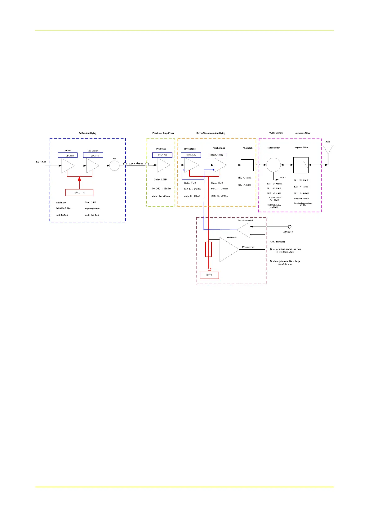
The transmitter circuit is mainly composed of:
RF Power Amplifier Circuit
Low-pass Filter Circuit (for suppressing harmonics)
Auto Power Control (APC) Circuit
Sampling Resistor
RF Power Amplifier Circuit
The carrier signal (TX signal) generated by TX voltage controlled oscillator (VCO) is modulated and
amplified via the buffer amplifier first, then passes through a pre-driver amplifier for primary power
amplification. After that, the signal goes to the driver amplifier (RD01) for further power amplification,
then the driver amplifier provides properly amplified signal to the final-stage amplifier (RD07) for final
power amplification. After amplified by multiple amplifiers, the TX signal will pass through a microstrip
matcher at the output end of final-stage amplifier to complete output impedance matching, so as to
reduce output power loss due to impedance mismatch. Then the TX signal will go to the low-pass filter
through TX/RX switch circuit.
Low-pass Filter Circuit (for suppressing harmonics)
The low-pass filter for suppressing harmonics is a high-order filter composed of lumped-parameter
inductors and capacitors. Via this filter, the spurious signal within the stop band can be attenuated as
much as possible while the in-band ripple is within the required range.
APC Circuit
In the APC circuit, the drain current from the driver amplifier and final-stage amplifier is converted to a