2
SYS
SIO
1
0
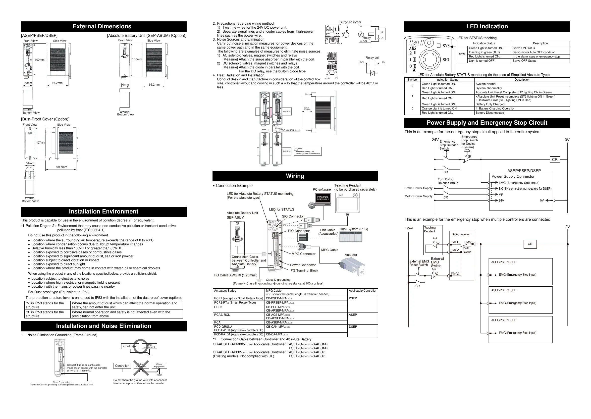
External Dimensions
[ASEP/PSEP/DSEP] [Absolute Battery Unit (SEP-ABUM) (Option)]
[Dust-Proof Cover (Option)]
Installation Environment
This product is capable for use in the environment of pollution degree 2
*1
or equivalent.
*1 Pollution Degree 2 : Environment that may cause non-conductive pollution or transient conductive
pollution by frost (IEC60664-1)
Do not use this product in the following environment.
Location where the surrounding air temperature exceeds the range of 0 to 40C
Location where condensation occurs due to abrupt temperature changes
Relative humidity less than 10%RH or greater than 85%RH
Location exposed to corrosive gases or combustible gases
Location exposed to significant amount of dust, salt or iron powder
Location subject to direct vibration or impact
Location exposed to direct sunlight
Location where the product may come in contact with water, oil or chemical droplets
When using the product in any of the locations specified below, provide a sufficient shield.
Location subject to electrostatic noise
Location where high electrical or magnetic field is present
Location with the mains or power lines passing nearby
For Dust-proof type (Equivalent to IP53)
The protection structure level is enhanced to IP53 with the installation of the dust-proof cover (option).
“5” in IP53 stands for the
structure
Where the amount of dust which can affect the normal operation and
safety, can not enter the unit.
“3” in IP53 stands for the
structure
Where normal operation and safety is not affected even with the
precipitation from above.
Installation and Noise Elimination
1. Noise Elimination Grounding (Frame Ground)
2. Precautions regarding wiring method
1) Twist the wires for the 24V DC power unit.
2) Separate signal lines and encoder cables from high-power
lines such as the power wire.
3. Noise Sources and Elimination
Carry out noise elimination measures for power devices on the
same power path and in the same equipment.
The following are examples of measures to eliminate noise sources.
1) AC solenoid valves, magnet switches and relays
[Measure] Attach the surge absorber in parallel with the coil.
2) DC solenoid valves, magnet switches and relays
[Measure] Attach the diode in parallel with the coil.
For the DC relay, use the built-in diode type.
4. Heat Radiation and Installation
Conduct design and manufacture in consideration of the control box
size, controller layout and cooling in such a way that the temperature around the controller will be 40C or
less.
Wiring
Connection Example
Actuators Series MPG Cable
□□□ shows the cable length. (Example:0505m)
Applicable Controller
RCP2 (except for Small Rotary Type) CB-PSEP-MPA□□□ PSEP
RCP2-RT□ (Small Rotary Type)
CB-RPSEP-MPA□□□
RCP3 CB-PCS-MPA□□□
CB-APSEP-MPA□□□
RCA2, RCL CB-ACS-MPA□□□
CB-APSEP-MPA□□□
ASEP
RCA CB-ASEP-MPA□□□
RCD-GRSNA
RCD-RA1DA (Applicable controllers D5)
CB-CAN-MPA□□□ DSEP
RCD-RA1DA (Applicable controllers D3)
CB-CA-MPA□□□
*1 Connection Cable between Controller and Absolute Battery
CB-APSEP-ABM005 ······· Applicable Controller : ASEP-C-□-□-□-0-ABUM□
PSEP-C-□-□-□-0-ABUM□
CB-APSEP-AB005 ········· Applicable Controller : ASEP-C-□-□-□-0-ABU□
(Existing models: Not complied with UL) PSEP-C-□-□-□-0-ABU□
LED indication
LED for STATUS teaching
LED for Absolute Battery STATUS monitoring (in the case of Simplified Absolute Type)
S
 Loading...


