L
10
21
9
L
10
21
9
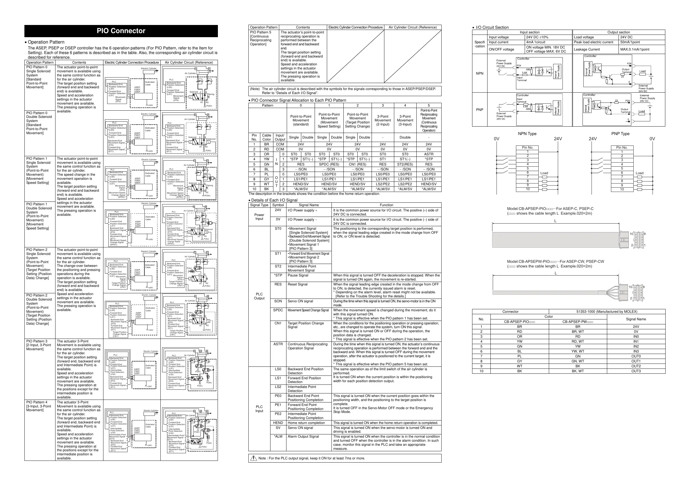
Model:CB-APSEPW-PIO□□□···For ASEP-CW, PSEP-CW
(□□□ shows the cable length L Example.020=2m)
Model:CB-APSEP-PIO□□□···For ASEP-C, PSEP-C
(□□□ shows the cable length L Example.020=2m)
PIO Connector
Operation Pattern
The ASEP, PSEP or DSEP controller has the 6 operation patterns (For PIO Pattern, refer to the Item for
Setting). Each of these 6 patterns is described as in the table. Also, the corresponding air cylinder circuit is
described for reference.
Operation Pattern Contents Electric C
linder Connection Procedure Air C
PIO Pattern 0
Single Solenoid
System
[Standard
Point-to-Point
Movement]
The actuator point-to-point
movement is available using
the same control function as
for the air cylinder.
The target position setting
(forward end and backward
end) is available.
Speed and acceleration
settings in the actuator
movement are available.
The pressing operation is
available.
PLC
+24V
Electric Cylinder
Dedicated
Cable
Movement
Signal
(ST0)
Forward End
Position Detection
(LS1)
Backward End
Position Detection
(LS0)
ASEP,
PSEP,
DSEP
R2R1
BA
Spring
Solenoid
Air Cylinder
PLC
P(Air)
Movement
Signal
(ST0)
Forward End
Position Detection
(LS1)
Backward End
Position Detection
(LS0)
PIO Pattern 0
Double Solenoid
System
[Standard
Point-to-Point
Movement]
+24V
Electric Cylinder
Dedicated
Cable
PLC
Backward End
Movement Signal
(ST0)
Forward End
Movement Signal
(ST1)
Forward End
Position Detection
(LS1)
Backward End
Position Detection
(LS0)
ASEP,
PSEP,
DSEP
R2R1
BA
Solenoid
Air Cylinder
Solenoid
PLC
P(Air)
Backward End
Movement Signal
(ST0)
Forward End
Movement Signal
(ST1)
Forward End
Position Detection
(LS1)
Backward End
Position Detection
(LS0)
PIO Pattern 1
Single Solenoid
System
(Point-to-Point
Movement)
[Movement
Speed Setting]
The actuator point-to-point
movement is available using
the same control function as
for the air cylinder.
The speed change in the
movement operation is
available.
The target position setting
(forward end and backward
end) is available.
Speed and acceleration
settings in the actuator
movement are available.
The pressing operation is
available.
+24V
Electric Cylinder
Dedicated
Cable
PLC
Movement Speed
Change Signal
(SPDC)
Movement
Signal
(ST0)
Forward End
Position Detection
(LS1)
Backward End
Position Detection
(LS0)
ASEP,
PSEP,
DSEP
Spring
R2
R1
BA
Solenoid
Air Cylinder
PLC
P(Air)
Forward End
Position Detection
(LS1)
Backward End
Position Detection
(LS0)
Movement Speed
Change Signal
(SPDC)
Movement
Signal
(ST0)
PIO Pattern 1
Double Solenoid
System
(Point-to-Point
Movement)
[Movement
Speed Setting]
+24V
PLC
Electric Cylinder
Dedicated
Cable
Backward End
Movement Signal
(ST0)
Forward End
Movement Signal
(ST1)
Forward End
Position Detection
(LS1)
Backward End
Position Detection
(LS0)
Movement Speed
Change Signal
(SPDC)
ASEP,
PSEP,
DSEP
R2
R1
BA
Solenoid
Solenoid
Air Cylinder
PLC
P(Air)
Backward End
Movement Signal
(ST0)
Forward End
Movement Signal
(ST1)
Forward End
Position Detection
(LS1)
Backward End
Position Detection
(LS0)
Movement Speed
Change Signal
(SPDC)
PIO Pattern 2
Single Solenoid
System
(Point-to-Point
Movement)
[Target Position
Setting (Position
Data) Change]
The actuator point-to-point
movement is available using
the same control function as
for the air cylinder.
The change-over between
the positioning and pressing
operations during the
operation is available.
The target position setting
(forward end and backward
end) is available.
Speed and acceleration
settings in the actuator
movement are available.
The pressing operation is
available.
+24V
Electric Cylinder
Dedicated
Cable
PLC
Forward End
Position Detection
(LS1)
Backward End
Position Detection
(LS0)
Target Position
Change Signal
(CN1)
Movement
Signal
(ST0)
ASEP,
PSEP,
DSEP
R2
R1
BA
Air Cylinder
PLC
P(Air)
P(Air)
Forward End
Position Detection
(LS1)
Backward End
Position Detection
(LS0)
Target Position
Change Signal
(CN1)
Movement
Signal
(ST0)
PIO Pattern 2
Double Solenoid
System
(Point-to-Point
Movement)
[Target Position
Setting (Position
Data) Change]
+24V
PLC
Electric Cylinder
Dedicated
Cable
Backward End
Movement Signal
(ST0)
Forward End
Movement Signal
(ST1)
Forward End
Position Detection
(LS1)
Backward End
Position Detection
(LS0)
Target Position
Change Signal
(CN1)
ASEP,
PSEP,
DSEP
R2
R1
B
A
Air Cylinder
PLC
P(Air)
P(Air)
Backward End
Movement Signal
(ST0)
Forward End
Movement Signal
(ST1)
Forward End
Position Detection
(LS1)
Backward End
Position Detection
(LS0)
Target Position
Change Signal
(CN1)
PIO Pattern 3
[2-Input, 3-Point
Movement]
The actuator 3-Point
Movement is available using
the same control function as
for the air cylinder.
The target position setting
(forward end, backward end
and Intermediate Point) is
available.
Speed and acceleration
settings in the actuator
movement are available.
The pressing operation at
the positions except for the
intermediate position is
available.
+24V
Electric Cylinder
Dedicated
Cable
PLC
Backward End
Movement Signal
(ST0)
Forward End
Movement Signal
(ST1)
Forward End
Position Detection
(LS1)
Backward End
Position Detection
(LS0)
Intermediate
Point Detection
(LS2)
ASEP,
PSEP,
DSEP
Air Cylinder
PLC
P(Air)
P(Air)
P(Air)
Backward End
Movement Signal
(ST0)
Forward End
Movement Signal
(ST1)
Forward End
Position Detection
(LS1)
Backward End
Position Detection
(LS0)
Intermediate
Point Detection
(LS2)
PIO Pattern 4
[3-Input, 3-Point
Movement]
The actuator 3-Point
Movement is available using
the same control function as
for the air cylinder.
The target position setting
(forward end, backward end
and Intermediate Point) is
available.
Speed and acceleration
settings in the actuator
movement are available.
The pressing operation at
the positions except for the
intermediate position is
available.
+24V
Dedicated
Cable
PLC
Electric Cylinder
Backward End
Movement Signal
(ST0)
Forward End
Movement Signal
(ST1)
Forward End
Position Detection
(LS1)
Backward End
Position Detection
(LS0)
Intermediate
Point Detection
(LS2)
Intermediate Point
Movement Signal
(ST2)
ASEP,
PSEP,
DSEP
Air Cylinder
PLC
P(Air)
P(Air)
P(Air)
Backward End
Movement Signal
(ST0)
Forward End
Movement Signal
(ST1)
Forward End
Position Detection
(LS1)
Backward End
Position Detection
(LS0)
Intermediate
Point Detection
(LS2)
Intermediate Point
Movement Signal
(ST2)
Operation Pattern Contents Electric C
linder Connection Procedure Air C
PIO Pattern 5
[Continuous
Reciprocating
Operation]
The actuator’s point-to-point
reciprocating operation is
performed between the
forward end and backward
end.
The target position setting
(forward end and backward
end) is available.
Speed and acceleration
settings in the actuator
movement are available.
The pressing operation is
available.
(Note) The air cylinder circuit is described with the symbols for the signals corresponding to those in ASEP/PSEP/DSEP.
Refer to “Details of Each I/O Si
nal”.
PIO Connector Signal Allocation to Each PIO Pattern
Pattern 0 1 2 3 4 5
Point-to-Point
Movement
(standard)
Point-to-Point
Movement
(Movement
Speed Setting)
Point-to-Point
Movement
(Target Position
Setting Change)
3-Point
Movement
(2-Input)
3-Point
Movement
(3-Input)
Point-to-Point
Reciprocating
Movement
(Continuous
Reciprocating
Operation
Single Double Single Double Single Double - Double -
1 BR COM 24V 24V 24V 24V 24V 24V
2 RD COM 0V 0V 0V 0V 0V 0V
3 OR
I
N
0 ST0 ST0 ST0 ST0 ST0 ST0 ST0 ST0 ASTR
4 YW 1 *STP
ST1()
*STP
ST1()
*STP
ST1()
ST1
ST1()
*STP
5 GN 2 RES SPDC
RES
6 BL 3
/SON /SON /SON /SON /SON /SON
7 PL
O
U
T
0 LS0/PE0 LS0/PE0 LS0/PE0 LS0/PE0 LS0/PE0 LS0/PE0
8 GY 1 LS1/PE1 LS1/PE1 LS1/PE1 LS1/PE1 LS1/PE1 LS1/PE1
9 WT 2 HEND/SV HEND/SV HEND/SV LS2/PE2 LS2/PE2 HEND/SV
10 BK 3 *ALM/SV *ALM/SV *ALM/SV *ALM/SV *ALM/SV *ALM/SV
The description in the brackets shows the condition before the home return operation.
Details of Each I/O Signal
Si
nal Name Function
Power
Input
24V
I/O Power supply It is the common power source for I/O circuit. The positive () side of
24V DC is connected.
0V
I/O Power supply It is the common power source for I/O circuit. The positive () side of
24V DC is connected.
PLC
Output
ST0 • Movement Signal
[Single Solenoid System]
•
Backward End Movement Signal
[Double Solenoid System]
• Movement Signal 1
[PIO Pattern 3]
The positioning to the corresponding target position is performed,
when the signal leading edge created in the mode change from OFF
to ON, or ON level is detected.
ST1 •
Forward End Movement Signal
• Movement Signal 2
[PIO Pattern 3]
ST2 Intermediate Point
Movement Si
nal
*STP Pause Signal When this signal is turned OFF the deceleration is stopped. When the
si
ain, the movement is re-started.
RES Reset Signal When the signal leading edge created in the mode change from OFF
to ON, is detected, the currently issued alarm is reset.
* Depending on the alarm level, alarm reset might not be available.
[Refer to the Trouble Shootin
for the details.]
SON Servo ON signal During the time when this signal is turned ON, the servo-motor is in the ON
mode.
SPDC
Movement Speed Change Signal
When the movement speed is changed during the movement, do it
with this signal turned ON.
* This si
nal is effective when the PIO pattern 1 has been set.
CN1 Target Position Change
Signal
When the conditions for the positioning operation or pressing operation,
etc., are changed to operate the system, turn ON this signal.
When this signal is turned ON or OFF during the operation, the
position data is changed.
* This si
nal is effective when the PIO pattern 2 has been set.
ASTR Continuous Reciprocating
Operation Signal
During the time when this signal is turned ON, the actuator’s continuous
reciprocating operation is performed between the forward end and the
backward and. When this signal is turned OFF during the movement
operation, after the actuator is positioned to the current target, it is
stopped.
* This si
nal is effective when the PIO pattern 5 has been set.
PLC
Input
LS0 Backward End Position
Detection
The same operation as of the limit switch of the air cylinder is
performed.
It is turned ON when the current position is within the positioning
width for each position detection output.
LS1 Forward End Position
Detection
LS2 Intermediate Point
Detection
PE0 Backward End Point
Positionin
Completion
This signal is turned ON when the current position goes within the
positioning width, and the positioning to the target position is
complete.
It is turned OFF in the Servo-Motor OFF mode or the Emergency
Stop Mode.
PE1 Forward End Point
Positionin
Completion
PE2 Intermediate Point
Positionin
Completion
HEND Home return completion This si
nal is turned ON when the home return operation is completed.
SV Servo ON signal This signal is turned ON when the servo-motor is turned ON and
drivin
is enabled.
*ALM Alarm Output Signal This signal is turned ON when the controller is in the normal condition
and turned OFF when the controller is in the alarm condition. In such
case, monitor this signal in the PLC and take an appropriate
measure.
Note : For the PLC output signal, keep it ON for at least 7ms or more.
I/O Circuit Section
Input section Output section
Specifi
-cation
Input voltage 24V DC 10% Load voltage 24V DC
Input current 4mA 1circuit Peak load electric current 50mA/1point
ON/OFF voltage
ON voltage MIN. 18V DC
OFF voltage MAX. 6V DC
Leakage Current MAX.0.1mA/1point
NPN
PNP
NPN Type PNP Type
Connecto
No.
Color
Signal Name
CB-APSEP-PIO□□□ CB-APSEP-PW□□□
1 BR BR 24V
2 RD BR, WT 0V
3 OR RD IN0
4 YW RD, WT IN1
5 GN YW IN2
6 BL YW, WT IN3
7 PL GN OUT0
8 GY GN, WT OUT1
9 WT BK OUT2
10 BK BK, WT OUT3
0V 24V
Pin No.
1
2
3
4
5
6
7
8
9
10
Load
24V 0V
Pin No.
1
2
3
4
5
6
7
8
9
10
Load
All manuals and user guides at all-guides.com

 Loading...


