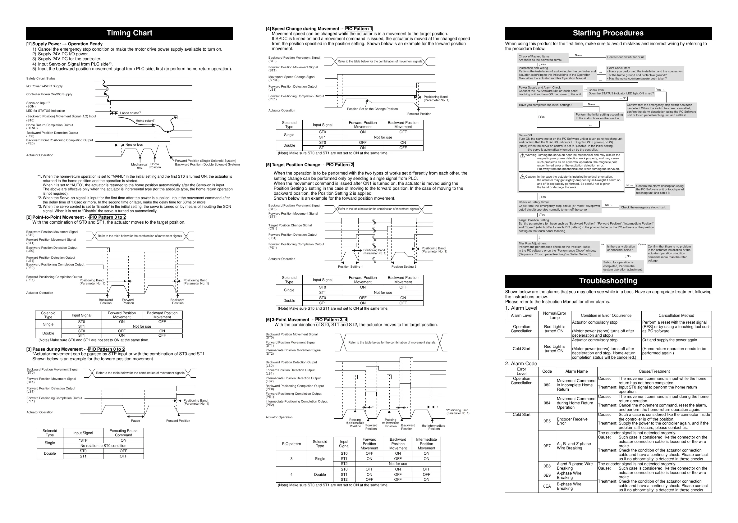
Timing Chart
[1] Supply Power → Operation Ready
1) Cancel the emergency stop condition or make the motor drive power supply available to turn on.
2) Supply 24V DC I/O power.
3) Supply 24V DC for the controller.
4) Input Servo-on Signal from PLC side*
3
.
5) Input the backward position movement signal from PLC side, first (to perform home-return operation).
*1. When the home-return operation is set to “MANU” in the initial setting and the first ST0 is turned ON, the actuator is
returned to the home position and the operation is started.
When it is set to “AUTO”, the actuator is returned to the home position automatically after the Servo-on is input.
The above are effective only when the actuator is incremental type (for the absolute type, the home return operation
is not required).
*2. When the Servo-on signal is input for the first time after the power is supplied, input the movement command after
the delay time of 1.6sec or more. In the second time or later, make the delay time for 60ms or more.
*3. When the servo control is set to “Enable” in the initial setting, the servo is turned on by means of inputting the SON
signal. When it is set to “Disable” the servo is turned on automatically.
[2] Point-to-Point Movement ···PIO Pattern 0 to 2
With the combination of ST0 and ST1, the actuator moves to the target position.
Solenoid
T
pe
Input Signal
Forward Position
Movemen
Backward Position
Movemen
Single
ST0 ON OFF
ST1 Not for use
Double
ST0 OFF ON
ST1 ON OFF
Make sure ST0 and ST1 are not set to ON at the same time.
[3] Pause during Movement ···PIO Pattern 0 to 2
*Actuator movement can be paused by STP input or with the combination of ST0 and ST1.
Shown below is an example for the forward position movement.
Solenoid
T
pe
Input Signal
Executing Pause
Command
Single
*STP ON
No relation to ST0 condition
Double
ST0 OFF
ST1 OFF
[4] Speed Change during Movement ···PIO Pattern 1
Movement speed can be changed while the actuator is in a movement to the target position.
If SPDC is turned on and a movement command is issued, the actuator is moved at the changed speed
from the position specified in the position setting. Shown below is an example for the forward position
movement.
Solenoid
T
pe
Input Signal
Forward Position
Movemen
Backward Position
Movemen
Single
ST0 ON OFF
ST1 Not for use
Double
ST0 OFF ON
ST1 ON OFF
Make sure ST0 and ST1 are not set to ON at the same time.
[5] Target Position Change ···PIO Pattern 2
When the operation is to be performed with the two types of works set differently from each other, the
setting change can be performed only by sending a single signal from PLC.
When the movement command is issued after CN1 is turned on, the actuator is moved using the
Position Setting 3 setting in the case of moving to the forward position. In the case of moving to the
backward position, the Position Setting 2 is applied.
Shown below is an example for the forward position movement.
Solenoid
T
pe
Input Signal
Forward Position
Movemen
Backward Position
Movemen
Single
ST0 ON OFF
ST1 Not for use
Double
ST0 OFF ON
ST1 ON OFF
Make sure ST0 and ST1 are not set to ON at the same time.
[6] 3-Point Movement ···PIO Pattern 3, 4
With the combination of ST0, ST1 and ST2, the actuator moves to the target position.
PIO pattern
Solenoid
Type
Input
Signal
Forward
Position
Movemen
Backward
Position
Movemen
Intermediate
Position
Movemen
3 Single
ST0 OFF ON ON
ST1 ON OFF ON
ST2 Not for use
4 Double
ST0 OFF ON OFF
ST1 ON OFF OFF
ST2 OFF OFF ON
Make sure ST0 and ST1 are not set to ON at the same time.
Starting Procedures
When using this product for the first time, make sure to avoid mistakes and incorrect wiring by referring to
the procedure below.
Troubleshooting
Shown below are the alarms that you may often see while in a boot. Have an appropriate treatment following
the instructions below.
Please refer to the Instruction Manual for other alarms.
1. Alarm Level
Alarm Level
Normal/Error
Lamp
Condition in Error Occurrence
Cancellation Method
Operation
Cancellation
Red Light is
turned ON.
Actuator compulsory stop
(Motor power (servo) turns off after
deceleration and stop.)
Perform a reset with the reset signal
(RES) or by using a teaching tool such
as PC software
Cold Start
Red Light is
turned ON.
Actuator compulsory stop
(Motor power (servo) turns off after
deceleration and stop. Home-return
completion status will be cancelled.)
Cut and supply the power again
(Home-return operation needs to be
performed again.)
2. Alarm Code
Erro
Level
Code Alarm Name Cause/Treatment
Operation
Cancellation
082
Movement Command
in Incomplete Home
Return
Cause: The movement command is input while the home
return has not been completed.
Treatment: Input ST0 signal to perform the home return
operation.
084
Movement Command
during Home Return
Operation
Cause: The movement command is input during the home
return operation.
Treatment: Cancel the movement command, reset the alarm,
and perform the home-return operation again.
Cold Start
0E5
Encoder Receive
Error
Cause: Such a case is considered like the connector inside
the controller is off the position.
Treatment: Supply the power to the controller again, and if the
problem still occurs, please contact us.
0E7
A-, B- and Z-phase
Wire Breaking
The encoder signal is not detected properl
.
Cause: Such case is considered like the connector on the
actuator connection cable is loosened or the wire
broke.
Treatment: Check the condition of the actuator connection
cable and have a continuity check. Please contact
us if no abnormality is detected in these checks.
0E8
A and B-phase Wire
Breaking
The encoder signal is not detected properl
.
Cause: Such case is considered like the connector on the
actuator connection cable is loosened or the wire
broke.
Treatment: Check the condition of the actuator connection
cable and have a continuity check. Please contact
us if no abnormality is detected in these checks.
0E9
A-phase Wire
Breaking
0EA
B-phase Wire
Breaking
Backward Position Movement Signal
(ST0)
Forward Position Movement Signal
(ST1)
Forward Position Detection Output
(LS1)
Forward Positioning Completion Output
(PE1)
ctuator Operation
Refer to the table below for the combination of movement signals.
Positioning Band
(Parameter No. 1)
Pause Forward Position
Position Set as the Change Position
Backward Position Movement Signal
(ST0)
Forward Position Movement Signal
(ST1)
Movement Speed Change Signal
(SPDC)
Forward Position Detection Output
(LS1)
Forward Positioning Completion Output
(PE1)
ctuator Operation
Refer to the table below for the combination of movement signals.
Positioning Band
(Parameter No. 1)
Forward Position
Backward Position Movement Signal
(ST0)
Forward Position Movement Signal
(ST1)
Target Position Change Signal
(CN1)
Forward Position Detection Output
(LS1)
Forward Positioning Completion Output
(PE1)
ctuator Operation
Refer to the table below for the combination of movement signals.
Positioning Band
(Parameter No. 1)
Positioning Band
(Parameter No. 1)
Position Setting 1 Position Setting 3
Backward Position Detection Output
(LS0)
Forward Position Detection Output
(LS1)
Backward Positioning Completion Output
(PE0)
Forward Positioning Completion Output
(PE1)
ctuator Operation
Backward Position Movement Signal
(ST0)
Forward Position Movement Signal
(ST1)
Refer to the table below for the combination of movement signals.
Positioning Band
(Parameter No. 1)
Positioning Band
(Parameter No. 1)
Forward
Position
Backward
Position
Backward
Position
Backward Position Detection Output
(LS0)
Forward Position Detection Output
(LS1)
Intermediate Position Detection Output
(LS2)
Backward Positioning Completion Output
(PE0)
Forward Positioning Completion Output
(PE1)
Intermediate Positioning Completion Output
(PE2)
ctuator Operation
Backward Position Movement Signal
(ST0)
Forward Position Movement Signal
(ST1)
Intermediate Position Movement Signal
(ST2)
Refer to the table below for the combination of movement signals.
*Positioning Band
(Parameter No. 1)
Passing
the Intermediate
Position
Passing
the Intermediate
Position
Forward
Position
Backward
Position
the Intermediate
Position
*
*
*
←
Check of Packed Items
Are there all the delivered items?
Contact our distributor or us.
→
Point Check Item
• Have you performed the installation and the connection
of the frame ground and protective ground?
• Has the noise countermeasure been taken?
Power Supply and Alarm Check
Connect the PC Software unit or touch panel
teaching unit and turn ON the power to the unit.
→
←
↓
→
Check Item
Does the STATUS indicator LED light ON in red?
Servo ON
Turn ON the servo-motor on the PC Software unit or touch panel teaching unit
and confirm that the STATUS indicator LED lights ON in green (SVON).
Targe t Positi on Setting
Set the parameters for those such as “Backward Position”, “Forward Position”, “Intermediate Position”
and “Speed” (which differ for each PIO pattern) in the position table on the PC software or the position
setting on the touch panel teaching.
Trial Run Adjustment
Perform the performance check on the Position Table
in the PC software or on the “Performance Check” window
(Sequence: “Touch panel teaching” → “Initial Setting” ).
Is there any vibration
or abnormal noise?
Set-up for operation is
completed, Perform the
system operation adjustment.
No→
←No
Yes→
Confirm that the emergency stop switch has been
cancelled. When the switch has been cancelled,
confirm the alarm description using the PC Software
unit or touch panel teaching unit and settle it.
No→
No→
No→
Yes→
↓Yes
↓Yes
↓Yes
Check of Safety Circuit
Check that the emergency stop circuit (or motor drivepower
cutoff circuit) operates normally to turn off the servo.
↓Yes
Check the emergency stop circuit.
↓No
Confirm that there is no problem
in the actuator installation or the
actuator operation condition
demands more than the rated
voltage.
Installation and Wiring
Perform the installation of and wiring for the controller and
actuator according to the instructions in the Operation
Manual for the actuator and this Operation Manual.
Have you completed the initial settings?
Perform the initial setting according
to the instructions on the window.
Confirm the alarm description using
the
PC Software unit or
touch panel
teaching unit and settle it.
Caution:
In the case the actuator is installed in vertical orientation,
the actuator may get slightly dropped by self-weight if servo on
and off is repeatedly performed. Be careful not to pinch
the hand or damage the work.
Warning:
Turning the servo on near the mechanical end may disturb the
magnetic pole phase detection work properly, and may cause
such problems as an abnormal operation, the magnetic pole
unconfirmed error or the excitation detection error.
Put away from the mechanical end when turning the servo on.
(Note) When the servo-on control is set to “Disable” in the initial setting,
the servo is automatically turned on by the controller.
Mechanical
end
Home
Position
1.6sec or less
6ms or less
Safety Circuit Status
I/O Power 24VDC Supply
Controller Power 24VDC Supply
Servo-on Input
*3
(SON)
LED for STATUS Indication
(Backward Position) Movement Signal (1,2) Input
(ST0)
Home Return Completion Output
(HEND)
Backward Position Detection Output
(LS0)
Backward Point Positioning Completion Output
(PE0)
ctuator Operation
*2
*1
Home return
Forward Position (Single Solenoid System)
Backward Position (Double Solenoid System)
All manuals and user guides at all-guides.com
 Loading...


