36
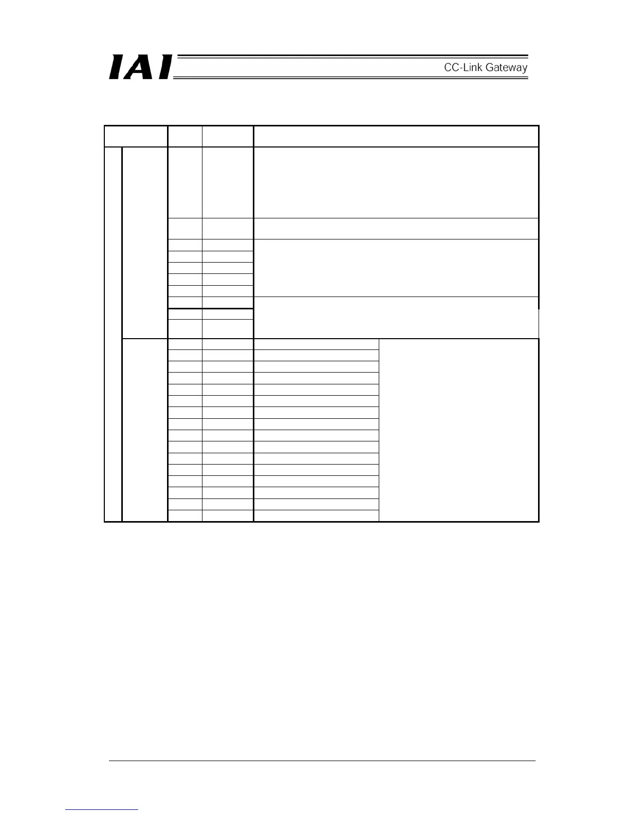
Details of input and output signal
Signal type Bit
Signal
name
Contents
15 MON
Link communication starts at ON, and stops at OFF.
When all of CFG15 to 0 (link connection axis selection) are OFF, do not
turn ON MON signal.
Further, while MON signal is ON, do not turn OFF all of CFG15 to 0.
When all of CFG15 to 0 are OFF and MON signal is ON, the gateway
unit becomes SIO link error, and the LED (T.ER) on the front of the unit
is lit.
14 - 8 -
This cannot be used.
Always turn this OFF (0).
7 NPS4
6 NPS3
5 NPS2
4 NPS1
3 NPS0
Use this in simple direct value/position No. designating mode.
In another mode, always turn this OFF (0).
Set number (0-16) of axes used in position No. designating mode by 5
bit binary.
2 PPS2
1 PPS1
Control
signal 0
0 PPS0
Use this in simple direct value/position No. designating mode.
In another mode, always turn this OFF (0).
Set I/O pattern (pattern 0-5) for position No. designating mode axis by
3 bit binary.
15 CFG15 Link ON Axis No.15
14 CFG14 14
13 CFG13 13
12 CFG12 12
11 CFG11 11
10 CFG10 10
9 CFG9 9
8 CFG8 8
7 CFG7 7
6 CFG6 6
5 CFG5 5
4 CFG4 4
3 CFG3 3
2 CFG2 2
1 CFG1 1
PLC output
Control
signal 1
0 CFG0 0
Set axis No. to which the link is
connected.
Link is connected at ON (1), and is
released at OFF (0).
Even while MON signal is ON,
ON/OFF is allowed.
(Note)
● Do not turn ON axis No. which is
not actually connected.
● Do not turn ON axes other than
settable axis No. which is selected
by the mode setting switch.
SIO link error occurs in each case.
 Loading...