62
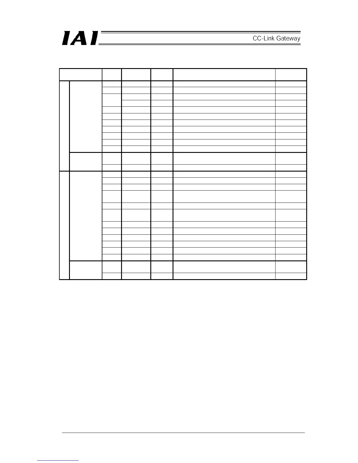
Detail of input and output signal
Signal type Bit
Signal
name
Pattern
No.
Contents Detail
b15 SON 0 – 4 Servo on command
b14 RES 0 – 4 Reset command
CSTR 0, 2, 3 Start command
b13
PWRT 1 Position data capturing command TEAC
b12 STP 0 – 4 Pause command
b11 HOME 0 – 4 Home return command
b10 BKRL 0, 2 – 4 Brake compulsory release
b9 JOG- 1 Jog- command
b8 JOG+ 1 Jog+ command
b7 JISL 1 Jog/inching changeover
Control
signal 0
b6 MOD 1 Teach mode command
b8–b0 PC*** 0 – 3
Command position No. is designated by
command position No.
PLC output
Command
position No.
b6–b0 ST0-ST6 4 Start position is designated by bit pattern.
b15 BALM 0 – 4 Battery voltage drop alarm
b14 ALM 0 – 4 Alarm occurring
b13 EMGS 0 – 4 On emergency stop
b12 SV 0 – 4
Operation preparation completion (Servo on
status)
b11 PEND 0, 2 – 4 Positioning completion
b11 WEND 1
Position data capturing command status
TEAC
b10 HEND 0 – 4 Home return completion
b9 RMDS 0 – 4 Operation mode status
b8 PZONE 0, 2 – 4 Position zone output monitor
b7 ZONE1 0, 4 Zone output monitor 1
b7 MODS 1 Teach mode status
Status
signal
b6 MOVE 0, 1 On moving
b8-b0 PM*** 0 – 3
Completed position No. is read by binary
number.
PLC input
Completed
position No.
b6-b0 PE0-PE6 4 Completed position is read by bit pattern.
 Loading...