61
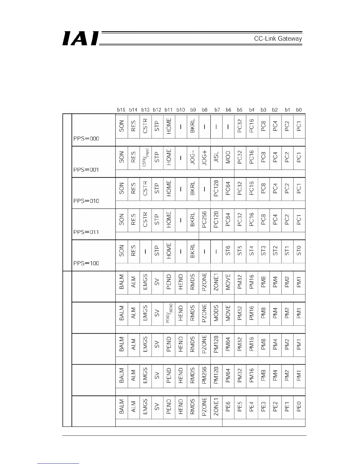
6.6.2 Assignment for each axis
Input and output signals for each axis position No. designated mode and those in simple direct value
mode are different from each other in size of region and its content. Further, in the position No.
designated mode, meaning of each bit depends on the pattern set by gateway control signal PPS.
(1) Control signal and status signal of position No. designated axis
Pattern 0
(Standard)
Pattern 1
(Teach)
Pattern 2
(Positioning 256
points)
Pattern 3
(Positioning 512
points)
Pattern 4
(Air cylinder)
PLC output RWw PLC input RWr
Pattern 0
Pattern 1
Pattern 2
Pattern 3
Pattern 4
Control signal Command position No.
Control signal Command position No.
Control signal Command position No.
Control signal Command position No.
Control signal Start position No.
Status signal Completed position No.
Status signal Completed position No.
Status signal Completed position No.
Completed position No.
Status signal Completed position No.
Status signal
 Loading...