Current Amperage
The current amperage should be divided into the control power capacity and motor power capacity.
Each power supply should be input from the control power supply connector and the motor power supply
connector on the gateway unit. However, it is necessary that the 0V of the control power supply and the
motor power supply are in common.
The necessary capacity of the current amperage should be figured out by [Total of control power capacity of
used units] + [Total of motor power capacity of used actuators].
It is necessary that the rated current of 24V power supply satisfies the rated current of the motor power
capacity and the peak current satisfies the maximum current of the motor power capacity. However, when
several axes get connected, unless all the actuators operates at the same time, the rated current and
maximum current would not flow at the same time, thus the calculation should not be simply the total of all
the axes.
The specifications related to the power capacities should be as shown below.
[Control Power Supply]
Item Specification
Power Supply Voltage 24V DC ±10%
Control Power Capacity
(for one unit)
Gateway unit
(terminal unit included)
RCON Gateway Unit
0.8A (Ethernet option: Not equipped)
1.0A (Ethernet option: Equipped)
SEL Unit 1.2A
24V Driver unit
Brake: Not equipped 0.2A
Brake: Equipped (one-axis type) 0.4A
Brake: Equipped (two-axis type) 0.6A
200V Driver uni
(200V power supply
unit included)
Brake: Not equipped 0.2A
Brake: Equipped 0.5A
Extension unit
SCON Extension Unit 0.1A
PIO/SIO/SCON Extension Unit 0.3A
PIO Unit 0.2A
Simple absolute unit (in common for all types) 0.2A
EC Connection Unit 0.1A
[24V Motor Power Supply]
Item
Actuator / Driver unit
Rated
Current
Max. current
Series Motor type
When
energy-saving
is set
Motor power capacity
(1 axis per actuator)
Stepper motor
/ RCON-PC
RCP2
RCP3
20P/20SP/28P
Without PowerCON
0.8A - -
28P
(Note 1)
/35P/42P/56P
1.9A - -
RCP4
RCP5
RCP6
28P/35P/42P
/42SP/56P
Without PowerCON
1.9A - -
With PowerCON 2.3A - 3.9A
Stepper motor
/ RCON-PCF
RCP2
RCP4
RCP5
RCP6
56SP/60P/86P
Without PowerCON
5.7A - -
AC servo motor
/ RCON-AC
RCA
RCA2
5W
Standard
/ Hi-accel./decel.
1.0A - 3.3A
10W
Standard
/ Hi-accel./decel.
/ Energy-saving
1.3A 2.5A 4.4A
20W 1.3A 2.5A 4.4A
20W (20S) 1.7A 3.4A 5.1A
30W 1.3A 2.2A 4.0A
RCL
2W
Standard
/ Hi-accel./decel.
0.8A - 4.6A
5W 1.0A - 6.4A
10W 1.3A - 6.4A
DC brush-less
motor
/ RCON-DC
RCD 3W Standard 0.7A - 1.5A
In-Rush Current
(Approx. 5ms)
Pulse motor / RCON-PC
8.3A
(with in-rush current limiting circuit)
Pulse motor / RCON-PCF
10.0A
with in-rush current limitin
circuit
Servo AC motor / RCON-AC
10.0A
with in-rush curren
limitin
circuit
Brushless DC motor / RCON-DC
10.0A
(with in-rush current limiting circuit)
Heat Generation
RCON-PC
PowerCON
: Not equipped
5.0W
PowerCON
: Not equipped
8.0W
RCON-PCF
PowerCON
: Equipped
19.2W
RCON-AC
Standard
/
High-acceleration
/deceleration
4.5W
RCON-DC Standard 3.0W
Note 1 Applicable Models: RCP2-RA3, RCP2-RGD3
If there is no fan unit equipped, operation can be performed
without derating in the temperature range between 0 and
40°C, but it is necessary to reduce the operation duty by 20%
in every 5°C in the temperature range between 40 and 55°C.
In case of fan unit equipped, operation can be performed
with no derating up to 55°C.
Restrictions in Unit Connection
(1) Number of 24V Driver Units to Connect
The maximum number of control axes to be connected should be 16 axes in the RCON system and 8
axes in the RSEL system.
From the structural perspective of the unit, it can accept connection without any upper limit, but make it
accept the number of axes described above of driver units at the maximum.
Have two gateway units or more in the construction when it is necessary to control number of axes
described above or more of actuators.
(2) Current Restrictions
Shown below is the restricting values of current for selecting calculation.
Check that the calculation result of the control power supply and motor power supply of each unit based
on the construction of RCON/RSEL system does not exceed the restricting values of current for selecting
calculation.
Also, the gateway units should not be included for the calculation.
Shown below is some examples for calculation.
[Control Power Supply] * The gateway units should not be included for the calculation.
Example 1
Actuator × 16 axes, All axes equipped with brake (2 axes/unit)
Driver unit (with brake) 0.6A × 8 = 4.8A ⇒ OK
Example 2
Actuator × 16 axes, All axes equipped with brake (1 axis/unit)
Driver unit (with brake) 0.4A × 16 = 6.4A ⇒ OK
Example 3
Actuator × 16 axes, All axes equipped with brake (2 axes/unit), All axes simple absolute type
Driver unit (with brake) 0.6A × 8 + Simple absolute 0.2A × 16 = 8.0A ⇒ OK
Example 4
Actuator × 16 axes, All axes equipped with brake (1 axis/unit), All axes simple absolute type
Driver unit (with brake) 0.4A × 16 + Simple absolute 0.2A × 16 = 9.6A ⇒ NG
[Motor Power Supply]
Example 5
RCON-PC (with PowerCON) × 16 axes
RCON-PC (with PowerCON) rated current 2.3A × 16 axes = 36.8A ⇒ OK
Example 6
When RCON-PCF × 16 axes or 6 axes
RCON-PCF rated current 5.7A × 16 axes = 91.2A ⇒ NG
RCON-PCF rated current 5.7A × 6 axes = 34.2A ⇒ OK
Example 7
RCON-PC (with no PowerCON), RCON-AC, RCON-DC
Rated current for all the units is low and it would not exceed current limit with 16 axes ⇒ OK
Example 8
RCON-PCF × 3 axes, RCON-PC (with PowerCON) × 7 axes, RCON-AC × 3 axes
5.7 × 3 + 2.3 × 7 + 1.3 × 3 = 37.1A ⇒ OK
Note When the operation pattern is to have all the axes operate acceleration and deceleration only and
the operation duty is 100%, it is necessary that the calculation is done with the maximum current
for the motor power supply.
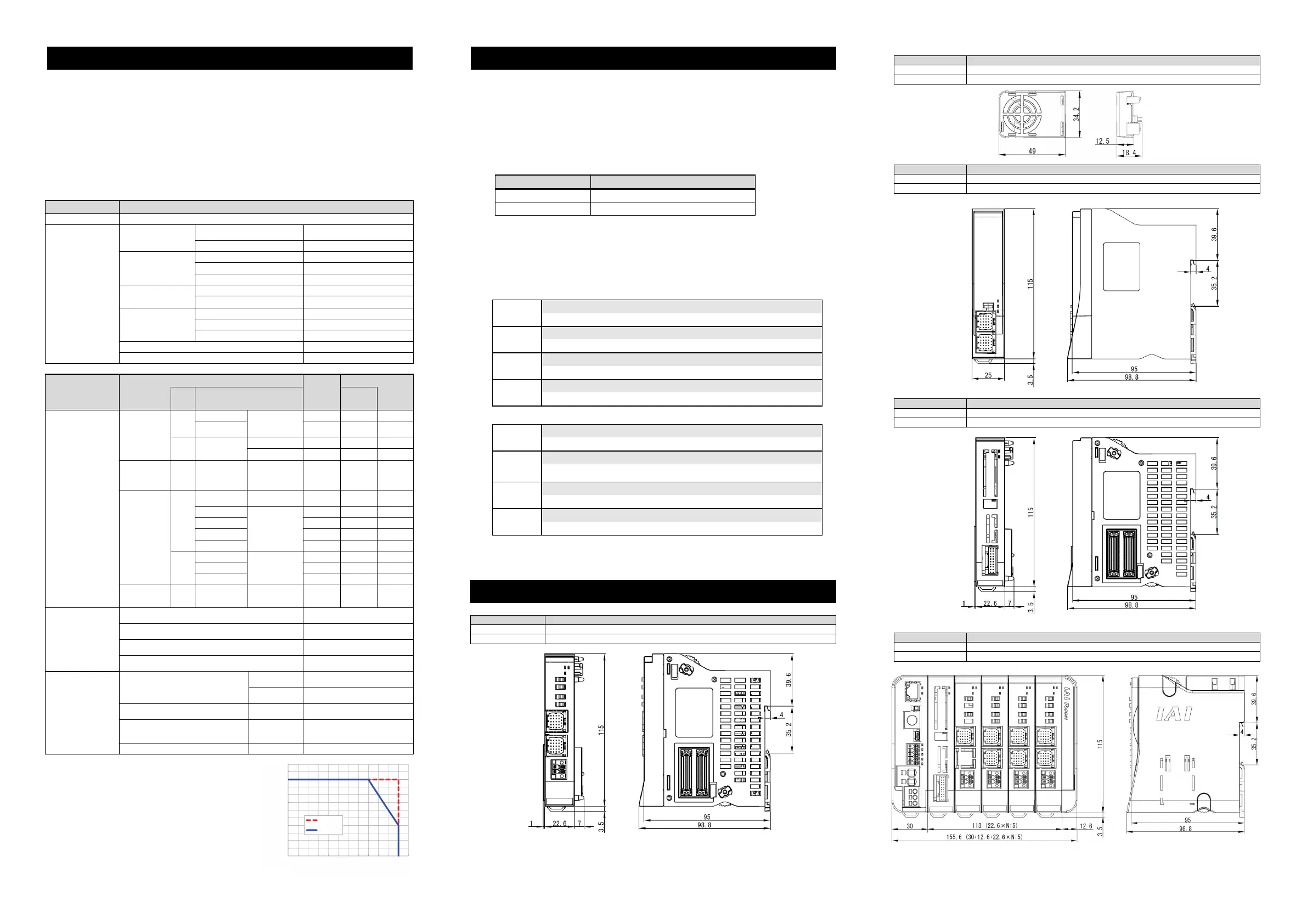
1. 24V Driver Unit (in common for P Driver Unit / A Driver Unit / D Driver Unit)
Item Specification
External Dimensions 22.6W × 115H × 95D [mm]
Mass Approx. 180g
2. Fan Unit
Item Specification
External Dimensions 34.2W × 49H × 12.5D [mm]
Mass Approx. 15g
3. Simple Absolute Unit
Item Specification
External Dimensions 22.6W × 115H × 95D [mm]
Mass Approx. 270g (included battery weight: 183g)
4. SCON Extension Unit
Item Specification
External Dimensions 22.6W × 115H × 95D [mm]
Mass Approx. 99g
5. When Units Linked
Item Specification
External Dimensions (42.6 + 22.6 × N) W × 115H × 95D [mm] N: Total number of driver units and extension units
Mass Approx. (206 + 180 × N1 + 99 × N2) g N1: Number of driver units, N2: Number of extensions units
Item Restricting Value of Current for Selecting Calculation
Control Power Supply (CP) 9.0A or less
Motor Power Supply (MP) 37.5A or less
External Dimensions
Model Code
Plate (Large)
Adhered
Position
Model Code
Plate (Large)
Adhered
Model Code
Plate (Large)
Adhered
Position
N: Total number of driver units and extension units
Operation Duty [%]
120
100
80
60
40
20
0
0
With Fan
With No Fan
10 20 30 40 50 60
Temperature Environment of Use [°C]

 Loading...


