RCON/RSEL Systems are capable to construct a system with the gateway allocated at the left end as the
interface for the field network connection and freely combine multiple driver units and extension units. There
is an order of allocation for each unit.
Gateway Unit (Left End) - Extension Unit (Right Side of Gateway Unit) - Driver Unit (
No Order among P/A/D
) - Terminal Unit (Right End)
Unit should be linked in the process shown below. (Make sure it gets linked before connected to the DIN rails.)
1) Twist the operation parts of the link upper parts and the link bottom parts towards the panel side and
place them at the panel side end.
2) Adjust the position of two units so the link upper parts come to Point [A], link bottom parts to [B] and the
four positioning bosses to [C] and all the six points fit to each other.
3) Once positioning is done, firmly insert the connectors at two points.
4) Twist the operation parts of the link upper parts and the link bottom parts towards the rear side till they
make click feeling.
Installation Environment
This product is capable for use in the environment of pollution degree 2
*1
or equivalent.
*1 Pollution Degree 2: Environment that may cause non-conductive pollution or transient conductive
pollution by frost (IEC60664-1)
1. Installation Environment
Do not use this product in the following environment.
• Location where the ambient temperature is out of the range between 0 and 55°C (with fan) or
0 and 40°C (with no fan)
• Location where condensation occurs due to abrupt temperature changes
• Location where relative humidity exceeds 85%RH
• Location exposed to corrosive gases or combustible gases
• Location exposed to significant amount of dust, salt or iron powder
• Location subject to direct vibration or impact
• Location exposed to direct sunlight
• Location where the product may come in contact with water, oil or chemical droplets
• Environment that blocks the air vent [Refer to section in Installation and Noise Elimination]
When using the product in any of the locations specified below, provide a sufficient shield.
• Location subject to electrostatic noise
• Location where high electrical or magnetic field is present
• Location with the mains or power lines passing nearby
2. Storage and Preservation Environment
The storage and preservation environment should comply with the same standards as those for the
installation environment.
In particular, when the machine is to be stored for a long time, pay close attention to environmental
conditions so that no condensation forms. Unless specially specified, moisture absorbency protection is
not included in the package when the machine is delivered. In the case that the machine is to be stored
and preserved in an environment where condensation is anticipated, take the condensation preventive
measures from outside of the entire package, or directly after opening the package.
Installation and Noise Elimination
For installation and noise elimination, refer to the first step guide for RCON Gateway Unit or RSEL Gateway
Unit.
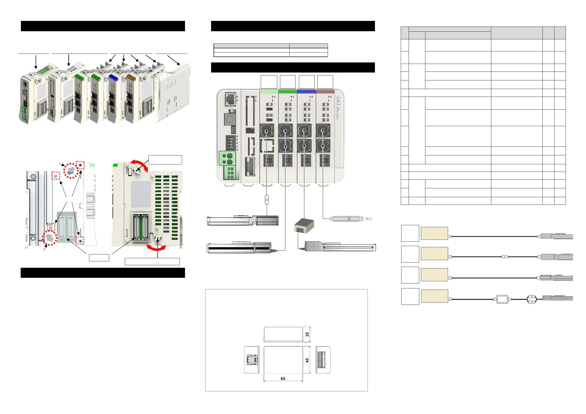
Wiring Layout for Motor/Encoder Cables
Note This wiring diagram shows an example for connection.
Required equipments, such as conversion cable and conversion unit, should differ
depending on the type of actuator.
Refer to “24V Driver Unit Connection Cable List” shown in the following page for
details.
[Conversion Unit]
For those actuators which cannot be connected using 24V Driver Unit connection cables
CB-ADPC-MPA□□□(-RB) and CB-RCAPC-MPA□□□(-RB) or a conversion cable CB-CAN-AJ002, it is
necessary to use this conversion unit and connection cable for each actuator in order to establish
connection.
24V Driver Unit Connection Cable List
No.
Actuator
Connection cable
(Note 2)
(-RB: Robot cable )
[Each actuator connection cable]
Conversion
unit
Wiring
diagram
Series Target type
(1)
RCP6
RCP6CR
RCP6W
RCP5
RCP5CR
RCP5W
Other than high thrust type
(Note 1)
CB-ADPC-MPA□□□(-RB) - A
(2) High thrust type
(Note 1)
CB-ADPC-MPA□□□(-RB)
CB-CAN-AJ002 (conversion cable)
- B
(3)
RCP4
RCP4CR
RCP4W
Gripper (GR*), ST4525E, SA3/RA3 CB-ADPC-MPA□□□(-RB) - A
(4) High thrust type
(Note 1)
CB-ADPC-MPA□□□(-RB)
CB-CAN-AJ002 (conversion cable)
- B
(5) Other than (3), (4)
CB-ADPC-MPA□□□(-RB)
CB-CAN-AJ002 (conversion cable)
- B
(6) RCP3 CB-RCAPC-MPA□□□(-RB) - C
(7)
RCP2
RCP2CR
RCP2W
RCP2 (standard type)
Rotary compact type
RCP2-RTBS/RTBSL/RTCS/RTCSL
CB-ADPC-MPA□□□(-RB)
[CB-RPSEP-MPA□□□]
Required
D
(8)
RCP2CR (clean room type),
RCP2W (dust-proof/splash-proof type)
Rotary (RT*) of above types
GRS/GRM/GR3SS/GR3SM of above types
CB-ADPC-MPA□□□(-RB) - A
(9)
All (standard / clean room /
dust-proof/splash-proof) types of
GRSS/GRLS/GRST/GRHM/GRHB
Short type (RCP2 only)
RCP2-SRA4R/SRGS4R/SRGD4R
CB-RCAPC-MPA□□□(-RB) - C
(10) High thrust type
(Note 1)
CB-ADPC-MPA□□□(-RB)
[CB-CF
-MPA□□□(-RB)]
Required
D
(11) Other than (7) to (10)
CB-ADPC-MPA□□□(-RB)
[CB-PSEP-MPA□□□]
Required
D
(12) RCA2/RCA2CR/RCA2W, RCL CB-RCAPC-MPA□□□(-RB) - C
(13) RCA2/RCA2CR/RCA2W (CNS option) CB-ADPC-MPA□□□(-RB) - A
(14)
RCA
RCACR
RCAW
Short type (RCA only)
RC
-SRA4R/SRGS4R/SRGD4R
CB-RCAPC-MPA□□□(-RB) - C
(15) Other than (14)
CB-ADPC-MPA□□□(-RB)
[CB-
SEP2-MPA□□□]
Required
D
(16) RCD RCD-RA1DA, RCD-GRSNA CB-ADPC-MPA□□□(-RB) - A
Note 1 Actuators using high-thrust pulse motor (56SP, 60P and 86P)
Note 2 Up to 20 m from each driver unit to the actuator, with or without the conversion unit.
However, the maximum length from the D driver unit to the RCD actuator will be 10 m.
Linking Units
Item Document Control
RCON Gatewa
Unit First Step Guide ME0382
RSEL Gatewa
Uni
First Step Guide ME0393
RCON
Controller Side
Actuator Side
Rear Side (Link)
Link Upper Parts
Operation Part
[C]
[A]
Link Bottom Parts Operation Part
[B]
Connector
Panel Side
(Unlink)
Rear Side
(Link)
Panel Side
(Unlink)
Wiring
A
Wiring
B
Wiring
C
Wiring
D
D
Driver
A
Driver
P
Driver
P
(High Thrust)
Driver Unit
RCA□ Actuato
RCP□ High Thrust Actuator
RCP□ Actuato
Conve
sion
Cable
Conversion
Unit
RCD Actuator
24V
Driver Unit
Motor/Encoder
Connector
CB-ADPC-MPA□□□(-RB)
Actuator
24V
Driver Unit
Motor/Encoder
Connector
CB-ADPC-MPA□□□(-RB)
Actuator
Conversion Cable
CB-CAN-AJ002
Order Separately
24V
Driver Unit
Motor/Encoder
Connector
CB-RCAPC-MPA□□□(-RB)
Actuator
24V
Driver Unit
Motor/Encoder
Connector
CB-ADPC-MPA□□□(-RB)
Actuator
Each Actuator
Connection Cable
Order Separately
Order Separately
RCM-CV
-APCS
Conversion
Unit

 Loading...


