Gateway unit Driver unit Driver unit
SIO connector
System I/O
connector
Motor
power
connector
Control
power
connector
Note 1
Control
power
24V
Stop
reset
switch
Stop
switch
Teaching pendant
Stop switch
Drive-source
cutoff
connector
Drive-source
cutoff
connector
Motor power Ⅰ
Motor power Ⅱ
Motor power Ⅰ
Motor power Ⅱ
High-side protection circuit
High-side protection circuit
High-side protection circuit
High-side protection circuit
24V
dedicated
for stop
circuit
Motor Power SupplyⅠ
Motor Power SupplyⅡ
High-Side Protection Circuit
System I/O
Connector
Motor Power Supply
Connector
Control
Power
Connector
Control
Power
Stop Reset
Switch
SEL Unit
High-Side Protection Circuit
ENB Detection
Enable Switch,
Door Switch, etc.
24V Driver Unit
Teaching Pendant
Teaching
Connector
Power Supply and Stop Circuit (Example)
In the diagram below shows a circuit related to a drive source cutoff. For RCON/RSEL System, 24V motor
power is supplied from the gateway unit, but the circuit related to the drive-source cutoff is on the driver unit
side.
• Each driver unit possesses a drive source cutoff circuit by semiconductor. The motor power should be
cut off by STOP Signal. The drive source cutoff circuit by semiconductor possesses features to detect
the overcurrent and to limit the in-rush current.
Note 1 RCON-GW : If nothing is connected to the SIO connector, S1 and S2 will be short-circuited in the controller.
RCON-GWG : If nothing is connected to the SIO connector, S1 and S2 will not be short-circuited in the controller.
To short-circuit, connect the supplied dummy plug DP-5 to the SIO connector.
Note ● When externally shutting off the motor drive source to comply with the safety category or the like, connect a contact
such as a relay to the wiring between the MPI* and MPO* terminals.
● The rating of the STOP-signal to be turned ON/OFF with the contact CR1 is 24 VDC / 10 mA or less.
● The CR1 coil current must be 0.1 A or less.
● When supplying power by turning ON/OFF 24 VDC, leave 0 V connected and supply/cut off +24 V.
Wiring Layout for SCON Connection Cables
When the SCON-CB/CGB RCON connected type controller is to be connected using an SCON Extension
Unit, conduct wiring as shown in the figure below. (SCON Controllers with model code SCON-CB/CGB-*-RC
are only those available to connect.)
RCON connection communication connector in SCON Controller has IN on lower end and OUT on upper
end. Pay attention not to connect other way around. It is necessary to connect the terminal connector
(RCON-EXT-TR) at the terminal.
Troubleshooting (LED Display)
In this section, describes for LED on each unit.
Utilize them to check normal operation status and recovery after error occurrence.
(1) 24V Driver Unit
Panel Display
Color Status Explanation
T RUN
GN
Illuminating
Inside bus communication in normal
conditions
Flashing
Waiting for initializing communication
Communication error at initialization
OR Illuminating Inside bus communication in error
SYS
GN
Illuminating Turning servo ON
OFF Turning servo OFF
RD Illuminating
Alarm being generated, During STOP
input
(2) Simple Absolute Unit
Panel Display
Color Status Explanation
SYS
GN Illuminating Operation in normal conditions
RD Illuminating Alarm being generated
STATUS1
GN Illuminating Home-return operation complete
RD Illuminating Home-return operation incomplete
STATUS0
GN Illuminating Battery fully charged
RD Illuminating Battery not connected
OR
(GN/RD)
Illuminating Battery charging
(3) SCON Controller (Field Network LED)
Refer to the instruction manual for SCON controller (ME0340) for the status display LED lamps (PWR,
SV, ALM and EMG).
Panel Display
Color Status Explanation
NS
GN
Illuminating Communication in normal conditions
Flashing
Startup ~
Initialization Communication Completed
OR Illuminating Communication Error Occurred
MS
GN Illuminating In Normal Condition
OR Illuminating Error Occurred
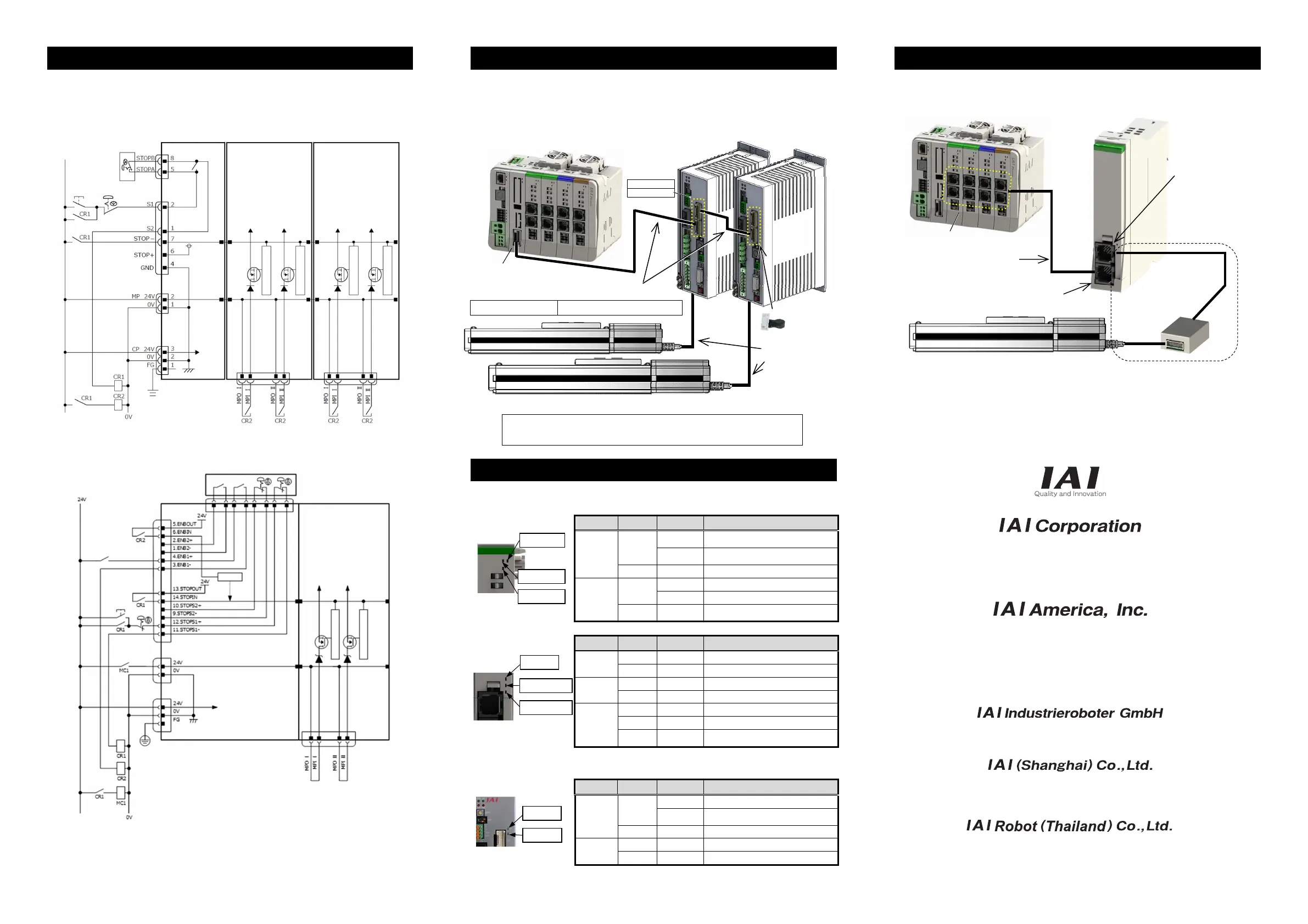
Wiring Layout for Simple Absolute Unit
When it is required to use a simple absolute unit (in common for P Driver and A Driver), conduct wiring as
shown in the figure below.
One unit of the simple absolute unit is necessary for one unit of an actuator.
Head Office: 577-1 Obane Shimizu-KU Shizuoka City Shizuoka 424-0103, Japan
TEL +81-54-364-5105 FAX +81-54-364-2589
website: www.iai-robot.co.jp/
Ober der Röth 4, D-65824 Schwalbach am Taunus, Germany
TEL 06196-88950 FAX 06196-889524
SHANGHAI JIAHUA BUSINESS CENTER A8-303, 808, Hongqiao Rd. Shanghai 200030, China
TEL 021-6448-4753 FAX 021-6448-3992
website: www.iai-robot.com
Technical Support available in USA, Europe and China
Head Office: 2690 W. 237th Street, Torrance, CA 90505
TEL (310) 891-6015 FAX (310) 891-0815
Chicago Office: 110 East State Parkway, Schaumburg, IL 60173
TEL(847) 908-1400 FAX (847) 908-1399
TEL (678) 354-9470 FAX (678) 354-9471
website: www.intelligentactuator.com
Atlanta Office: 1220 Kennestone Circle, Suite 108, Marietta, GA 30066
825 PhairojKijja Tower 7th Floor, Debaratana RD., Bangna-Nuea, Bangna, Bangkok 10260, Thailand
TEL +66-2-361-4458 FAX +66-2-361-4456
website:www.iai-gmbh.de
website:www.iai-robot.co.th
Upper End: OUT
Lower End: IN
Total Cable Length: 10m Max. Length of Cables between Devices: 3m Max.
Servo-pressing type (SCON-CB/CGB-F) and
PLC feature equipped type (SCON-LC/LCG) are not available to connect.
Manual No.: ME0383-2A
SYSⅠ LED
SYSⅡ LED
T RUN LED
STATUS1 LED
SYS LED
STATUS0 LED
MS
NS
RCON System
RSEL S
stem
Cable for each actuator
Refer to SCON-CB
Instruction Manual
RCON System
RSEL System
Actuator
SCON-CB/CGB Controlle
Connection Cable: CB-RE-CTL□□□
(Supplied with SCON-CB/CGB-*-RC)
RCON Connection
Communication
Connector
Terminal Connector:
RCON-EXT-TR
(Supplied with
SCON Extension
Unit)
SCON Extension Unit
Simple Absolute Unit
Driver Connector (CONT)
Actuator
Connector (MPG)
CB-ADPC-MPA005
(Supplied with
Simple Absolute Unit)
RCON System
RSEL System
Actuato
Driver Unit
For the wiring of this part, refer to the
24V Driver Unit connection cable list
in “Wiring Layout for Motor/Encoder
Cables”.

 Loading...


