Application Relation
Each PN controller can be connected to one or more slots, but each slot is as-
signed to only one PN controller. The „Application relation“ column shows the index
and the IP address of the connected PN controller for that slot.
If the PROFINET device is operated as S2 device, the index and IP addresses of
both PN controllers are displayed in the column.
Output/Input
A slot can consist of output and input bytes.
Length
Size of the data bytes
State
The state is indicated by a description and a color:
Green: a controller is connected and the slot state is GOOD
Orange: a controller is connected and the slot state is BAD, e.g. the controller is
i n S T O P.
Red: no controller is connected
Cycle time
Cycle duration
9.2.3 “Device slot“ module
The module „device slot“ is only available underneath a device node.
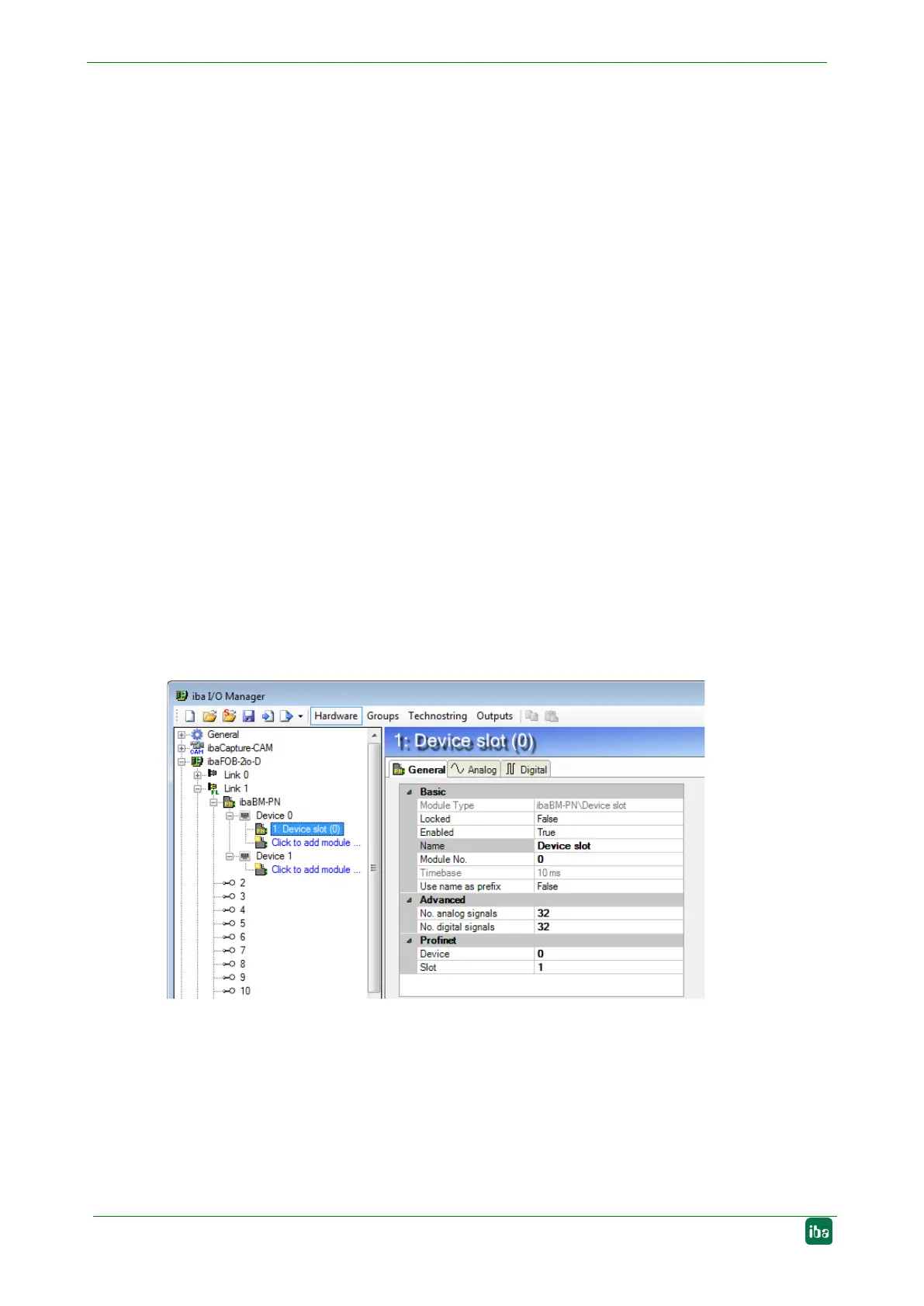
9.2.3.1 “General“ tab
Figure 19: “Device slot“ module – “General“ tab
Basic settings
Module type, Locked, Enabled, Name, Timebase, Use name as prefix
see chapter 9.2.1.1.
Module No.
Logical module no. for clearly referencing of signals, e.g. in expressions in virtual
modules and ibaAnalyzer.