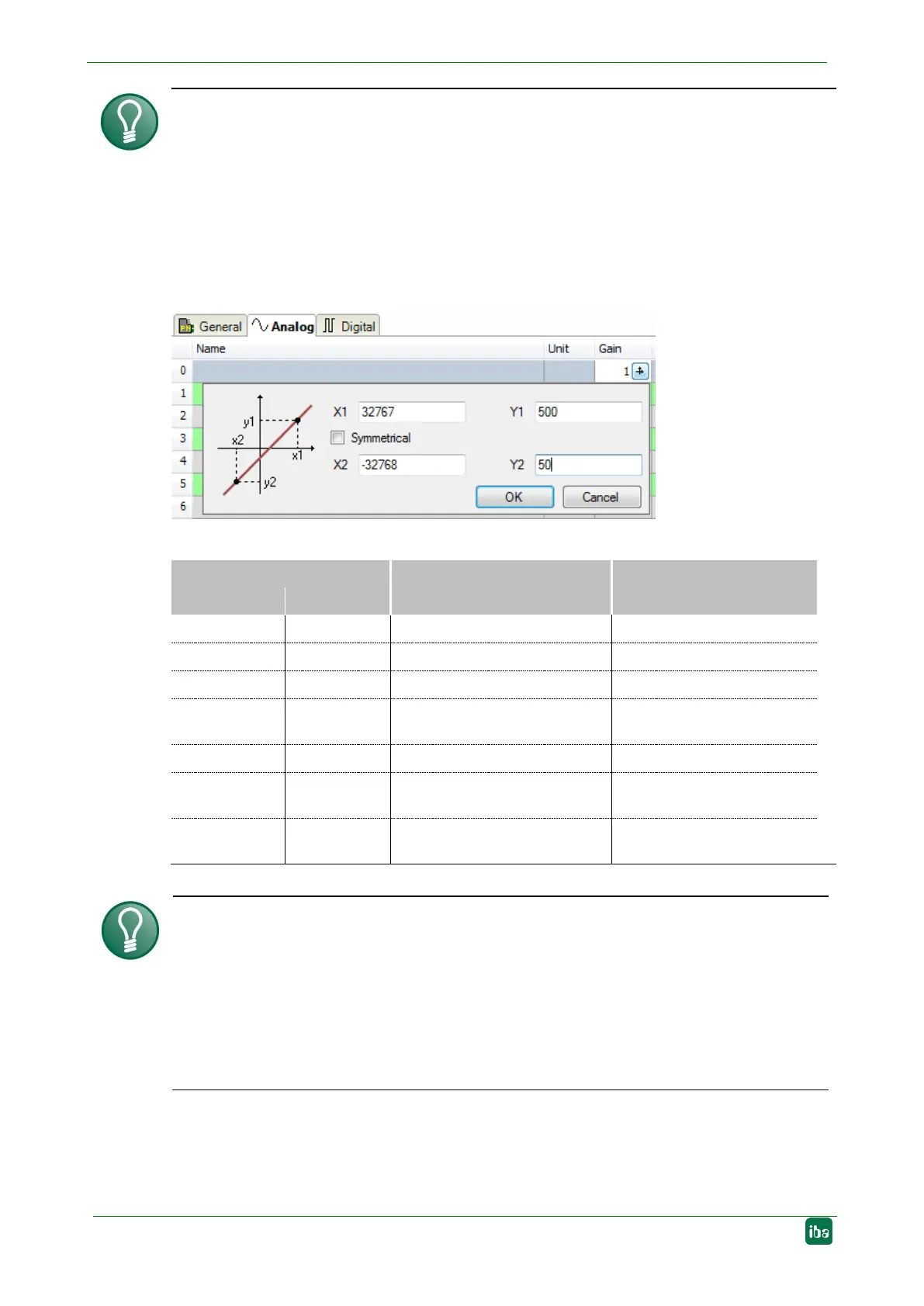
Example
For a SIMATIC ET200 AI/AO module, a +/
-10V signal with a value range of -27648 …
-10V … +10V) is transferred.
Within the control program, the transferred
value has a physical
meaning (e. g. temperature 50°C … 500°C). You can choose by
version of the value. The no unit value is then recorded with the physi-
For making the calculation of Gain/Offset easier, an auxiliary dialog appears when click-
ing on the co
-ordinate cross icon in the "Gain" or "Offset" field. In this dialog, you only
enter two points in the line equation.
Gain and offset are then calculated automatically.
the signal. Available data types for analog signals:
Data type
Description Value range
Big Endian Little Endian
BYTE BYTE 8 Bit without plus/minus sign 0 to 255
INT_B INT 16 Bit with plus minus sign -32768 to 32767
WORD_B WORD 16 Bit without plus/minus sign
0 to 65535
DINT_B DINT 32 Bit with plus/minus sign -2147483647 to
2147483647
DWORD_B DWORD 32 Bit without plus/minus sign 0 to 4294967295
FLOAT_B FLOAT IEEE754; Single Precision;
32 Bit floating point
1.175·10
-38
to 3.403·10
38
S5_FLOAT_B S5_FLOAT Simatic S5 Float Format,
32 Bit
±0.1701412 e+39 ...
±0.1469368 e-38
Tip
When entering the signals of a device in sequential order, only the data types have to
be
selected for all signals. The byte addresses of the signals are then calculated auto-
matically. For this purpose, please enter only for the first signal of the desired
device
yte address into the address column and then click on the column
header. Starting with the first add
ress (where the cursor is positioned) and considering
all data types, the addresses of the other signals of this
device are filled in automati-
Active
Only when this option is selected, the signal is acquired and also considered when
checking the number of licensed signals.
 Loading...