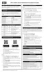
3.4 Sequence of operation
3.4.1 Heating Mode
Upon a call for heat from the thermostat:
R to W1 or W2 is energized.
The External Pump relay is closed, energizing the external pump if connected (required when
connecting the air handling appliance to a tankless water heater or SL series boiler).
The TT (boiler on Heat 1) contacts close creating a call for heat at the boiler.
The fan is energized and:
Operates at W1 or W2 speed.
Fan speed ramps up to the maximum value of its W1 range value or W2 range value.
When a demand for heat is satisfied, the system:
Opens TT (or Heat 1) to remove the boiler's call for heat.
Continues to operate the fan for 45 seconds; also operates the pump contacts for 30 seconds.
3.4.2 Cooling Mode
Upon a call for cooling from the thermostat:
R to Y1 or Y2 is energized
The fan is energized and:
Operates at Y1 or Y2 speed.
Energizes the O/B terminal if there is a heat pump.
When cooling demand is satisfied, the air handling appliance:
Opens the compressor S1 and /or S2 contacts, and de-energizes O/B if there is a heat pump.
The fan continues to operate for 45 seconds.
3.4.3 Heat Pump Mode
Upon a call for heat from a heat pump:
R to Y1 or Y2 is energized.
R to O/B remains de-energized.
The fan is energized and:
Operates at Y1 or Y2 speed.
Operates a low speed for 60 seconds.
3.4 Sequence of operation
 Loading...