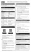
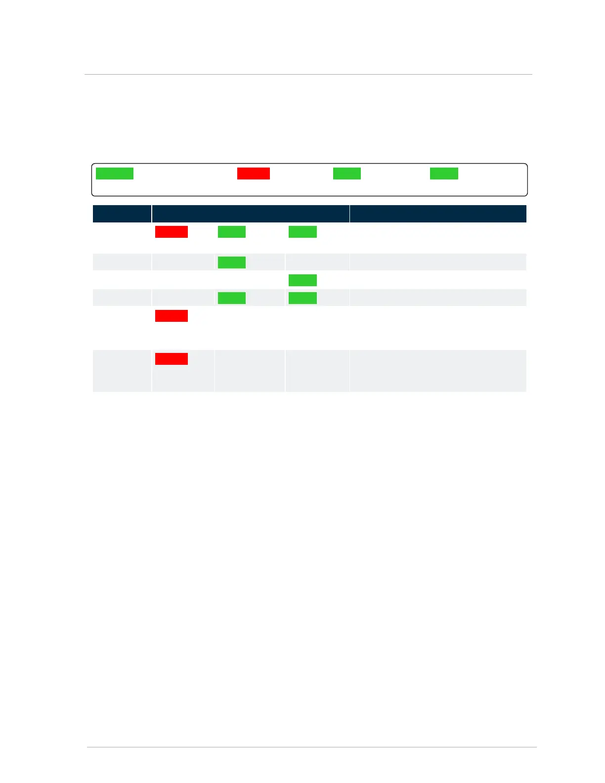
3.5 LED status indicators
The appliance displays four LED indicators, each representing an operating status.
POWER (Green background) FAULT (Red
background)
HEAT (Green
background)
COOL(Green
background)
State LED(s) Description
Standby FAULT HEAT COOL Each LED blinks on and off in a
“chasing” sequence.
Heating HEAT LED displays a steady state.
Cooling COOL LED displays a steady state.
Fan only (G) HEAT COOL Short synchronized flashing.
Warning FAULT LED flashes on. The appliance will
continue to operate; however, certain
operations may not function correctly.
Fault FAULT LED displays a steady state. The
appliance will not service heat or cooling
calls.
Table 12 Status indicators
Built-in diagnostics feature
The appliance contains a built-in diagnostic feature that enables you to obtain information on settings,
faults, and errors.
To view diagnostics:
1.
Insert a USB stick into the controller, wait approximately 10 seconds, and then remove the USB
stick.
The controller generates a text file that contains all the settings and any faults or warnings that
are present on the appliance.
2.
To view the text file, insert the USB stick into any computer, and open the generated text file
with “Wordpad” or a similar program.
The file name will be: “AHUxxxxx.TXT”, where “xxxxx” is the serial number of the controller.
3.5 LED status indicators
 Loading...