IBM Internal Use Only
5. Single step the counters by repeatedly pressing START.
Check that all counters contain the same value after
each impression.
Operational Patch Panel Test
The logical functions available at the operational patch
panels may be checked by using the plus one (+1) hubs, the
TEST 1 OUT and TEST 2 OUT hubs on the test patch
panel, and any available counter.
Lamp Test
1. Press POWER ON, MACHINE RESET and LAMP TEST.
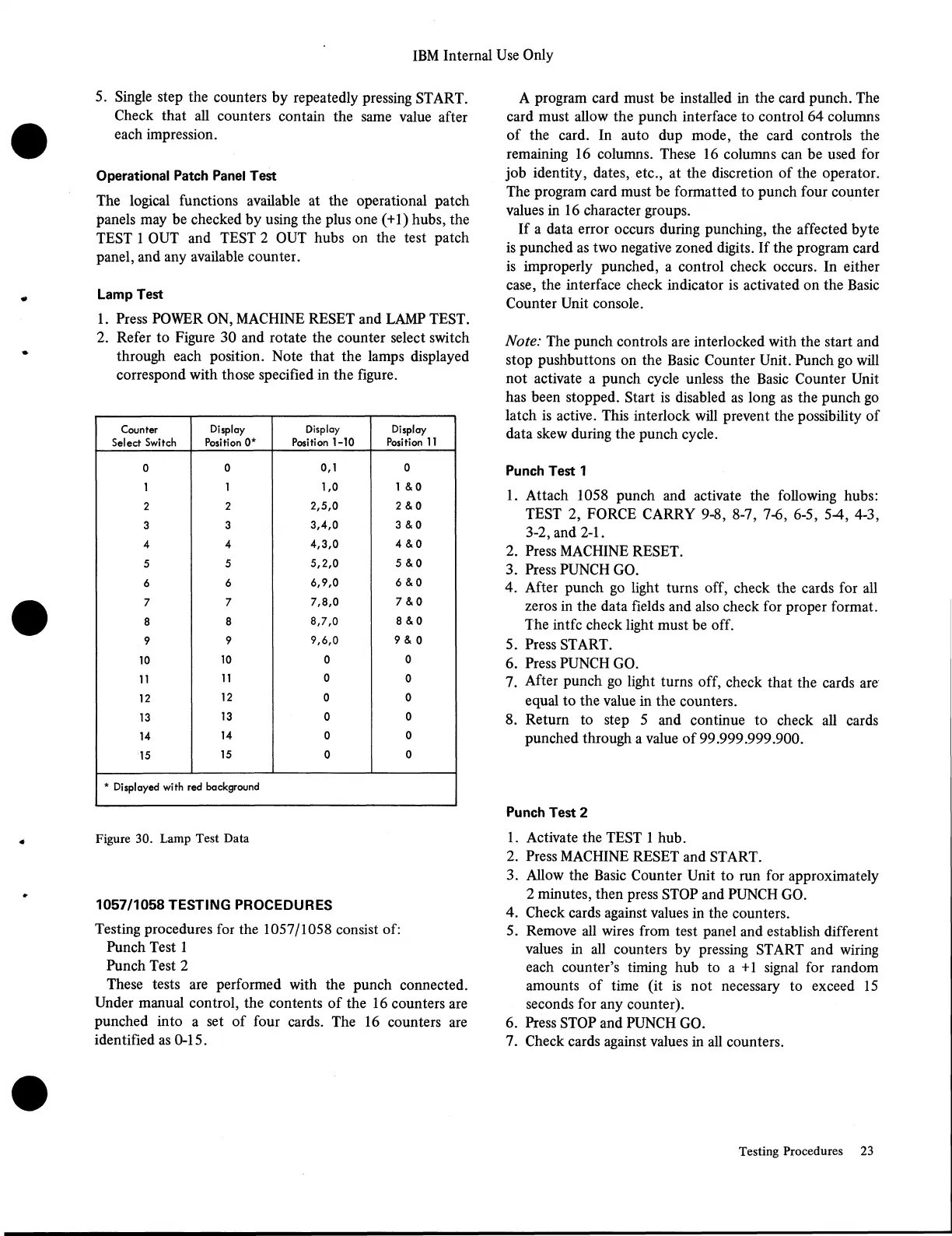
2. Refer to Figure 30 and rotate the counter select switch
through each position. Note that the lamps displayed
correspond with those specified in the figure.
Counter
Select Switch
Display
Position 0*
Display
Position 1-10
Display
Position 11
0
0
0,1
0
1 1
1,0
1 &0
2
2 2,5,0 2 & 0
3
3
3,4,0 3 & 0
4
4
4,3,0 4 & 0
5
5
5,2,0
5 & 0
6
6
6,9,0
6 & 0
7
7
7,8,0
7 & 0
8
8
8,7,0
8 & 0
9
9 9,6,0 9 & 0
10
10 0
0
11
11
0
0
12
12
0 0
13
13 0
0
14
14
0
0
15
15
0
0
* Displayed with red background
Figure 30. Lamp Test Data
1057/1058 TESTING PROCEDURES
Testing procedures for the 1057/1058 consist of:
Punch Test 1
Punch Test 2
These tests are performed with the punch connected.
Under manual control, the contents of the 16 counters are
punched into a set of four cards. The 16 counters are
identified as 0-15.
A program card must be installed in the card punch. The
card must allow the punch interface to control 64 columns
of the card. In auto dup mode, the card controls the
remaining 16 columns. These 16 columns can be used for
job identity, dates, etc., at the discretion of the operator.
The program card must be formatted to punch four counter
values in 16 character groups.
If a data error occurs during punching, the affected byte
is punched as two negative zoned digits. If the program card
is improperly punched, a control check occurs. In either
case, the interface check indicator is activated on the Basic
Counter Unit console.
Note: The punch controls are interlocked with the start and
stop pushbuttons on the Basic Counter Unit. Punch go will
not activate a punch cycle unless the Basic Counter Unit
has been stopped. Start is disabled as long as the punch go
latch is active. This interlock will prevent the possibility of
data skew during the punch cycle.
Punch Test 1
1. Attach 1058 punch and activate the following hubs:
TEST 2, FORCE CARRY 9-8, 8-7, 7-6, 6-5, 5-4, 4-3,
3-2, and 2-1.
2. Press MACHINE RESET.
3. Press PUNCH GO.
4. After punch go light turns off, check the cards for all
zeros in the data fields and also check for proper format.
The intfc check light must be off.
5. Press START.
6. Press PUNCH GO.
7. After punch go light turns off, check that the cards are
equal to the value in the counters.
8. Return to step 5 and continue to check all cards
punched through a value of 99.999.999.900.
Punch Test 2
1. Activate the TEST 1 hub.
2. Press MACHINE RESET and START.
3. Allow the Basic Counter Unit to run for approximately
2 minutes, then press STOP and PUNCH GO.
4. Check cards against values in the counters.
5. Remove all wires from test panel and establish different
values in all counters by pressing START and wiring
each counter’s timing hub to a +1 signal for random
amounts of time (it is not necessary to exceed 15
seconds for any counter).
6. Press STOP and PUNCH GO.
7. Check cards against values in all counters.
Testing Procedures 23