IBM Internal Use Only
Appendix D. Operational Patch Panel 1
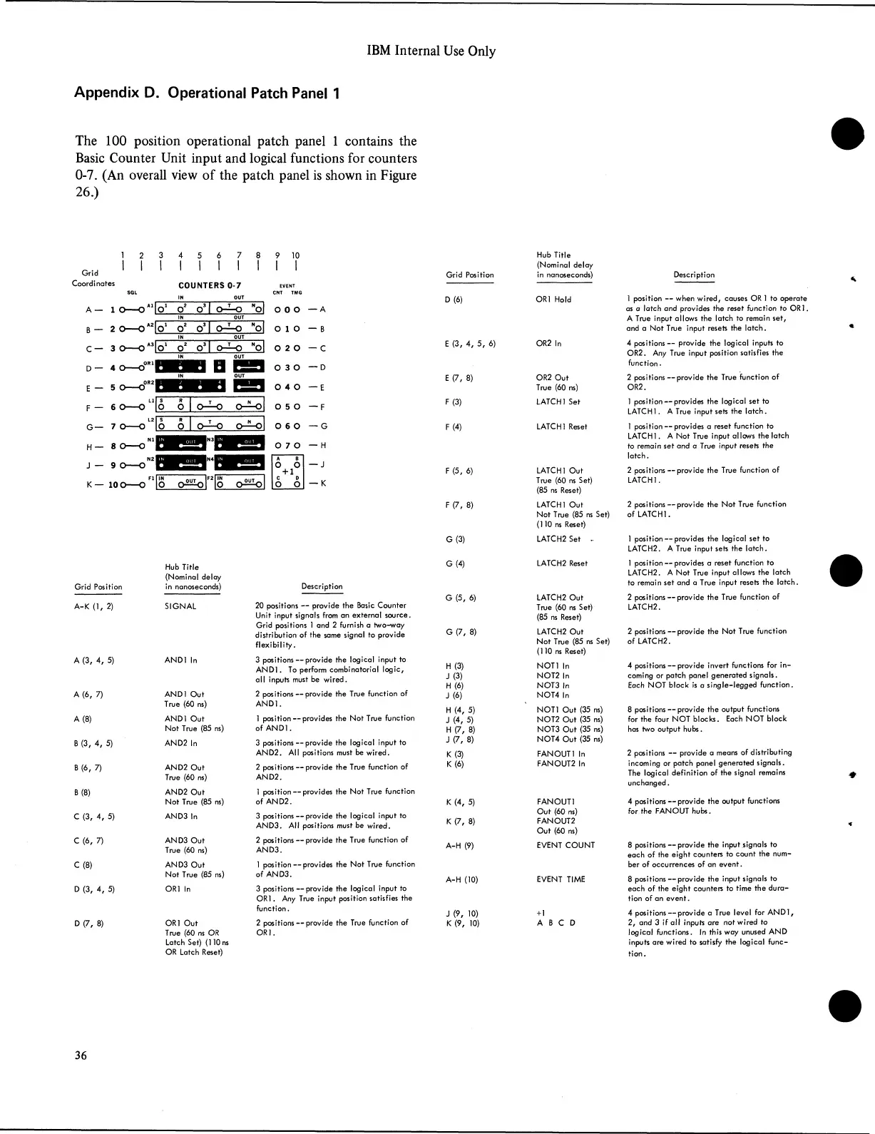
The 100 position operational patch panel 1 contains the
Basic Counter Unit input and logical functions for counters
0-7. (An overall view of the patch panel is shown in Figure
26.)
9 10
Grid Position
Hub Title
(Nominal delay
in nanoseconds)
A-K (1, 2)
A (3, 4, 5)
A (6, 7)
A (8)
B (3, 4, 5)
B (6, 7)
B (8)
C (3, 4, 5)
C (6, 7)
C (8)
D (3, 4, 5)
D (7, 8)
Hub Title
(Nominal delay
in nanoseconds)
SIGN AL
CNT TMG
D (6) OR1 Hold
O 0 o
— A
O 1 0
— B
0 2 0
— C
E (3, 4, 5, 6)
OR2 In
0 3 0
— D
E (7, 8)
OR2 Out
0 4 0
— E
True (60 ns)
0 5 0
— F
F(3)
LATCH 1 Set
0 6 0
— G
F (4)
LATCH 1 Reset
0 7 0
— H
A B
o o
— J
+ 1
C D
o o
— K
F (5, 6)
LATCH 1 Out
True (60 ns Set)
(85 ns Reset)
F (7, 8)
LATCH 1 Out
Not True (85 ns
(110 ns Reset)
G(3)
LATCH2 Set ••
G (4)
LATCH2 Reset
AND1 Out
True (60 ns)
AND1 Out
Not True (85 ns)
AND2 In
AND2 Out
True (60 ns)
AND2 Out
Not True (85 ns)
AND3 In
AN D3 Out
True (60 ns)
AN D3 Out
Not True (85 ns)
OR1 In
OR1 Out
True (60 ns OR
Latch Set) (110 ns
OR Latch Reset)
Description
20 positions — provide the Basic Counter
Unit input signals from an external source.
Grid positions 1 and 2 furnish a two-way
distribution of the same signal to provide
flexibility.
3 positions — provide the logical input to
AND1. To perform combinatorial logic,
all inputs must be wired.
2 positions — provide the True function of
AND1.
1 position — provides the Not True function
of AND1.
3 positions — provide the logical input to
AND2. All positions must be wired.
2 positions — provide the True function of
AND2.
1 position — provides the Not True function
of AND2.
3 positions — provide the logical input to
AND3. All positions must be wired.
2 positions — provide the True function of
AND3.
1 position — provides the Not True function
of AN D3.
3 positions — provide the logical input to
OR1. Any True input position satisfies the
function.
2 positions — provide the True function of
O R].
G (5, 6)
G (7, 8)
H (3)
J (3)
H (6)
J (6)
H (4, 5)
J (4, 5)
H (7, 8)
J (7, 8)
K (3)
K (6)
K (4, 5)
K (7, 8)
A-H (9)
A-H (10)
J (9, 10)
K (9, 10)
LATCH2 Out
True (60 ns Set)
(85 ns Reset)
LATCH2 Out
Not True (85 ns Set)
(110 ns Reset)
NOT1 In
NOT2 In
NOT3 In
NOT4 In
NOT1 Out (35 ns)
NOT2 Out (35 ns)
NOT3 Out (35 ns)
NOT4 Out (35 ns)
FAN OUT 1 In
FANOUT2 In
FANOUT1
Out (60 ns)
FANOUT2
Out (60 ns)
EVENT COUNT
+ 1
A B C D
Description
1 position — when wired, causes OR 1 to operate
as a latch and provides the reset function to OR1.
A True input allows the latch to remain set,
and a Not True input resets the latch.
4 positions— provide the logical inputs to
OR2. Any True input position satisfies the
function.
2 positions — provide the True function of
OR2.
1 position — provides the logical set to
LATCH 1. A True input sets the latch.
1 position — provides a reset function to
LATCH1. A Not True input allows the latch
to remain set and a True input resets the
latch.
2 positions — provide the True function of
LATCH 1.
2 positions — provide the Not True function
of LATCH 1.
1 position — provides the logical set to
LATCH2. A True input sets the latch.
1 position — provides a reset function to
LATCH2. A Not True input allows the latch
to remain set and a True input resets the latch.
2 positions — provide the True function of
LATCH2.
2 positions — provide the Not True function
of LATCH2.
4 positions — provide invert functions for in
coming or patch panel generated signals.
Each NOT block is a single-legged function.
8 positions — provide the output functions
for the four NOT blocks. Each NOT block
has two output hubs.
2 positions — provide a means of distributing
incoming or patch panel generated signals.
The logical definition of the signal remains
unchanged.
4 positions — provide the output functions
for the FANOUT hubs.
8 positions — provide the input signals to
each of the eight counters to count the num
ber of occurrences of an event.
8 positions — provide the input signals to
each of the eight counters to time the dura
tion of an event.
4 positions — provide a True level for AND1,
2, and 3 if all inputs are not wired to
logical functions. In this way unused AND
inputs are wired to satisfy the logical func
tion.
36