IBM Internal Use Only
Appendix E. Operational Patch Panel 2
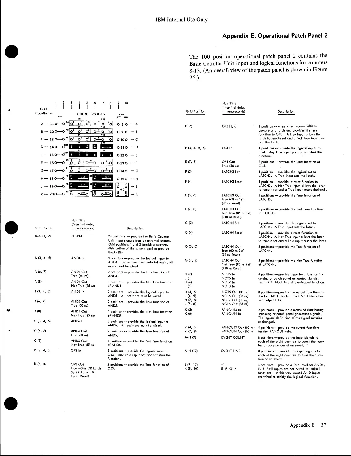
The 100 position operational patch panel 2 contains the
Basic Counter Unit input and logical functions for counters
8-15. (An overall view of the patch panel is shown in Figure
26.)
1 2
i i
3
4
1
5
6 7
8 9 10
Grid 1 1
1
1
1 1 1 1
1 1
Coordi nates
COUNTERS 8-15
EVENT
SGL
IN
OUT
CNT TMG
A — 110
----
0 A4|
|o‘
o2
o3|
o —-o
"o|
O 8 O — A
IN
OUT
B — 12.0
----
O *5
|o‘ o 2
0 3|
o —o
■o|
0 9 0 — B
IN
OUT
C — 13 0
----
0 A6|
IfiL
o 2
- o i l
o — —o
"oj
0 1 0 0 — c
Hub Title
(Nominal delay
Grid Position in nanoseconds) Description
D (6)
OR3 Hold
1 position— when wired,couses OR3 to
operate as a latch and provides the reset
function to OR3. A True input allows the
latch to remain set and a Not True input re
sets the latch.
E (3, 4, 5, 6)
OR4 In
4 positions — provide the logical inputs to
OR4. Any True input position satisfies the
function.
E (7, 8)
OR4 Out
True (60 ns)
2 positions — provide the True function of
OR4.
F (3)
LATCH3 Set
1 position — provides the logical set to
LATCH3. A True input sets the latch.
F (4) LATCH3 Reset
1 position — provides a reset function to
LATCH3. A Not True input allows the latch
to remain set and a True input resets the latch
F (5, 6)
LATCH3 Out
True (60 ns Set)
(85 ns Reset)
2 positions — provide the True function of
LATCH3.
Grid Position
Hub Title
(Nominal delay
in nanoseconds)
Description
i
<
SIGNAL
20 positions — provide the Basic Counter
Unit input signals from an external source.
Grid positions 1 and 2 furnish a two-way
distribution of the same signal to provide
flexibility.
A (3, 4, 5)
AND4 In
3 positions — provide the logical input to
AND4. To perform combinatorial logic, all
inputs must be wired.
A (6, 7)
AND4 Out
True (60 ns)
2 positions — provide the True function of
AND4.
A (8)
AND4 Out
Not True (85 ns)
1 position — provides the Not True function
of AND4.
B (3, 4, 5)
AND5 In
3 positions — provide the logical input to
AND5. All positions must be wired.
B (6, 7) AND5 Out
True (60 ns)
2 positions — provide the True function of
AND5.
B (8) AND5 Out
Not True (85 ns)
1 position — provides the Not True function
of AND5.
C (3, 4, 5)
AND6 In
3 positions — provide the logical input to
AND6. All positions must be wired.
C (6, 7)
AND6 Out
True (60 ns)
2 positions — provide the True function of
AND6.
C (8)
AN D6 Out
Not True (85 ns)
1 position — provides the Not True function
of AND6.
D (3, 4, 5)
OR3 In
3 positions — provide the logical input to
OR3. Any True input position satisfies the
function.
D (7, 8)
OR3 Out
True (60 ns OR Latch
Set) (110 ns OR
Latch Reset)
2 positions — provide the True function of
OR3.
F (7, 8)
LATCH3 Out
2 positions — provide the Not True function
Not True (85 ns Set)
(110 ns Reset)
of LATCH3.
G(3)
LATCH4 Set
1 position — provides the logical set to
LATCH4. A True input sets the latch.
G(4)
LATCH4 Reset
1 position — provides a reset function to
LATCH4. A Not True input allows the latch
to remain set and a True input resets the latch
G (5, 6)
LATCH4 Out
2 positions — provide the True function of
True (60 ns Set)
(85 ns Reset)
LATCH4.
G (7, 8)
LATCH4 Out
2 positions — provide the Not True function
Not True (85 ns Set)
(110 ns Reset)
of LATCH4.
H (3) NOT5 In
4 positions — provide input functions for in
-1(3)
NOT6 In
coming or patch panel generated signals.
H (6)
NOT7 In
Each NOT block is a single-legged function.
J(6)
NOT8 In
H (4, 5) NOT5 Out (35 ns)
8 positions — provide the output functions for
J (4, 5)
NOT6 Out (35 ns)
the four NOT blocks. Each NOT block has
H (7, 8)
NOT7 Out (35 ns)
two output hubs.
J (7, 8)
NOT8 Out (35 ns)
K (3)
FANOUT3 In
2 positions — provide a means of distributing
K (6)
FANOUT4 In
incoming or patch panel generated signals.
The logical definition of the signal remains
unchanged.
K (4, 5)
FANOUT3 Out (60 ns) 4 positions — provide the output functions
K (7, 8) FANOUT4 Out (60 ns)
for the FANOUT hubs.
A-H (9)
EVENT COUNT
8 positions — provide the input signals to
each of the eight counters to count the num
ber of occurrences of an event.
A-H (10)
EVENT TIME
8 positions — provide the input signals to
each of the eight counters to time the dura
tion of an event.
J (9, 10)
+1 4 positions — provide a True level for AND4,
K (9, 10)
E F G H 5, 6 if all inputs are not wired to logical
functions. In this way unused AND inputs
are wired to satisfy the logical function.
37Appendix E