IBM Internal Use Only
IBM Basic Counter Unit
PURPOSE AND FUNCTION
Data Processing Management is concerned with optimizing
the use of a computing center installation. Their need for
the system is to:
Improve performance.
Evaluate requirements for expansion.
Determine the effects of upgrading the system to a larger
and faster system.
Evaluate programming improvements.
The IBM Basic Counter Unit (Frontispiece) measures the
various activities of a system and provides data for
analyzing a system’s performance.
The Basic Counter Unit consists of 16 counters. Each
counter is 11 decimal digits wide and counts or times events
at the maximum rate of 1 MHz. Counter output is obtained
by visual display or by punched card.
To meet the wide range of measurement applications, the
Basic Counter Unit incorporates a patch panel of combina
torial logic. The user selects time inputs, incident counts,
logic functions, or combinations of these by wiring the
patch panel. Input signals to the Basic Counter Unit are
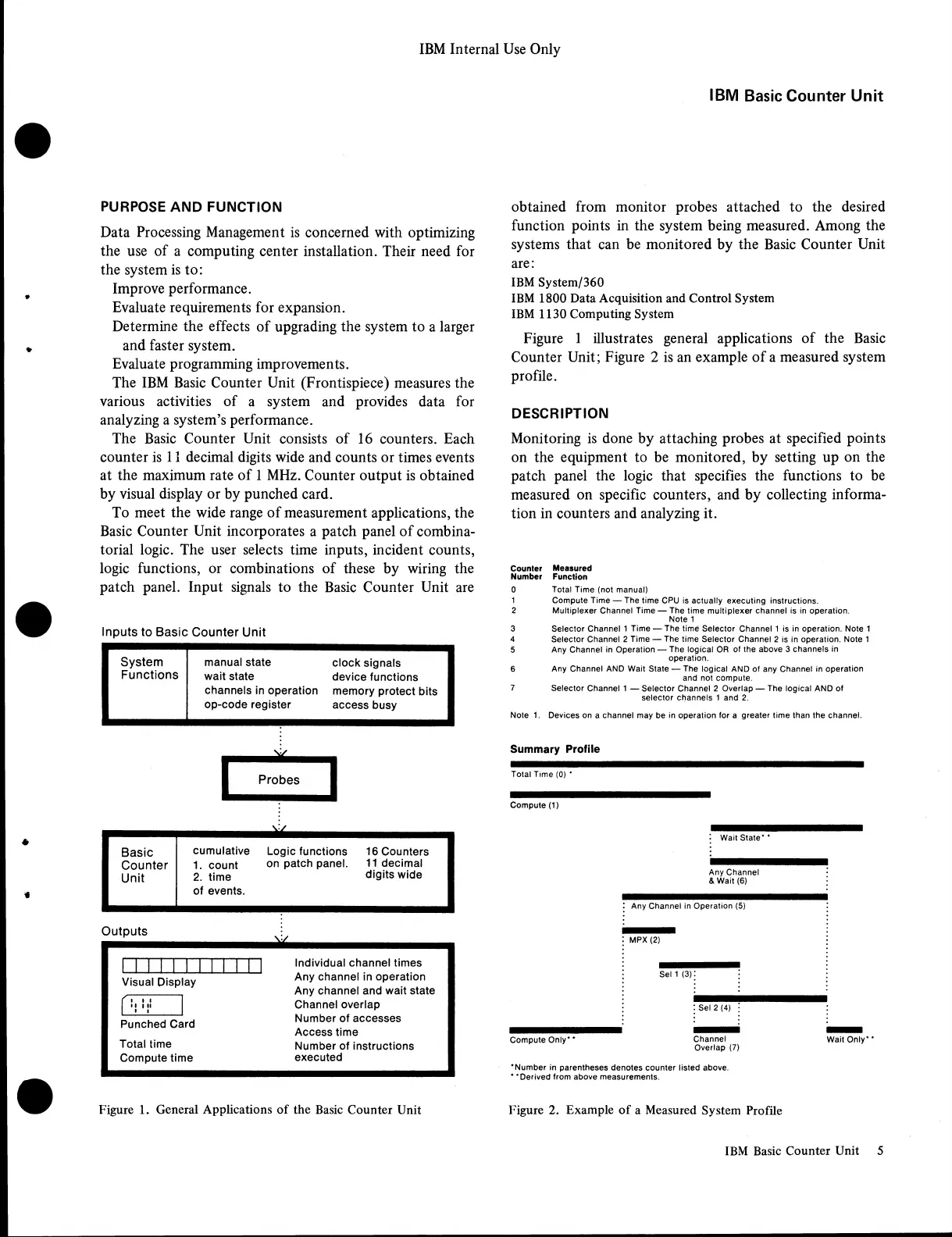
Inputs to Basic Counter Unit
System
manual state
clock signals
Functions
wait state
device functions
channels in operation
memory protect bits
op-code register
access busy
V/
I Probes
J
Basic
cumulative
Logic functions
16 Counters
Counter
1. count
on patch panel.
11 decimal
Unit
2. time
digits wide
of events.
Outputs
]" ~| | Individual channel times
Visual Display
Any channel in operation
Any channel and wait state
Channel overlap
Punched Card
Number of accesses
Access time
Total time
Number of instructions
Compute time
executed
Figure 1. General Applications of the Basic Counter Unit
obtained from monitor probes attached to the desired
function points in the system being measured. Among the
systems that can be monitored by the Basic Counter Unit
are:
IBM System/360
IBM 1800 Data Acquisition and Control System
IBM 1130 Computing System
Figure 1 illustrates general applications of the Basic
Counter Unit; Figure 2 is an example of a measured system
profile.
DESCRIPTION
Monitoring is done by attaching probes at specified points
on the equipment to be monitored, by setting up on the
patch panel the logic that specifies the functions to be
measured on specific counters, and by collecting informa
tion in counters and analyzing it.
Counter Measured
Number Function
0 Total Time (not manual)
1 Compute Time — The time CPU is actually executing instructions.
2 Multiplexer Channel Time — The time multiplexer channel is in operation.
Note 1
3 Selector Channel 1 Time — The time Selector Channel 1 is in operation. Note 1
4 Selector Channel 2 Time — The time Selector Channel 2 is in operation. Note 1
5 Any Channel in Operation — The logical OR of the above 3 channels in
operation.
6 Any Channel AND Wait State — The logical AND of any Channel in operation
and not compute.
7 Selector Channel 1 — Selector Channel 2 Overlap — The logical AND of
selector channels 1 and 2.
Note 1. Devices on a channel may be in operation for a greater time than the channel.
Summary Profile
Total Time (0) *
Compute (1)
Wait State* *
Any Channel
& Wait (6)
Any Channel in Operation (5)
MPX (2)
Sel 1 (3)
Sel 2 (4) j
Compute Only** Channel Wait Only**
Overlap (7)
‘ Number in parentheses denotes counter listed above.
* ‘ Derived from above measurements.
Figure 2. Example of a Measured System Profile
IBM Basic Counter Unit 5