IBM Internal Use Only
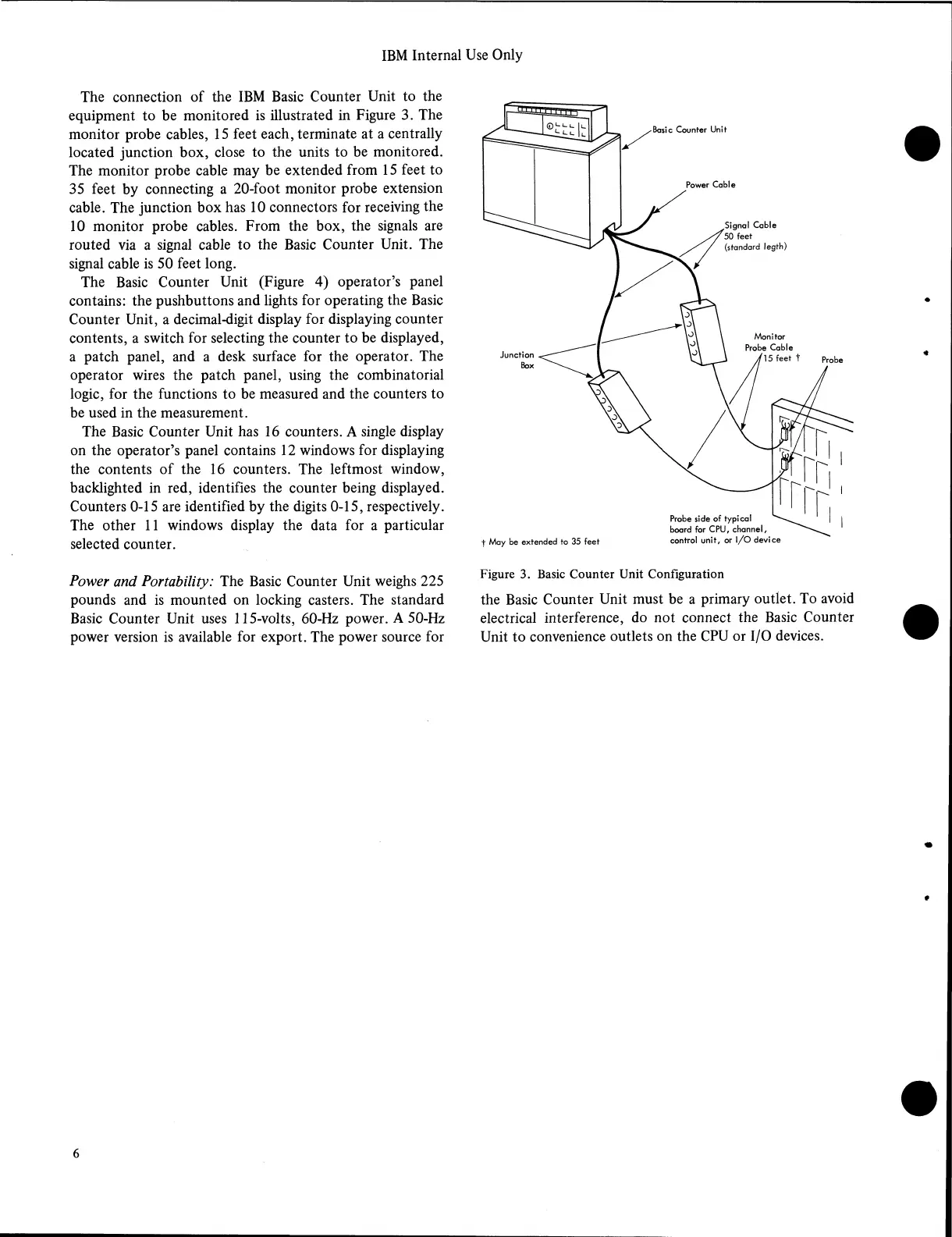
The connection of the IBM Basic Counter Unit to the
equipment to be monitored is illustrated in Figure 3. The
monitor probe cables, 15 feet each, terminate at a centrally
located junction box, close to the units to be monitored.
The monitor probe cable may be extended from 15 feet to
35 feet by connecting a 20-foot monitor probe extension
cable. The junction box has 10 connectors for receiving the
10 monitor probe cables. From the box, the signals are
routed via a signal cable to the Basic Counter Unit. The
signal cable is 50 feet long.
The Basic Counter Unit (Figure 4) operator’s panel
contains: the pushbuttons and lights for operating the Basic
Counter Unit, a decimal-digit display for displaying counter
contents, a switch for selecting the counter to be displayed,
a patch panel, and a desk surface for the operator. The
operator wires the patch panel, using the combinatorial
logic, for the functions to be measured and the counters to
be used in the measurement.
The Basic Counter Unit has 16 counters. A single display
on the operator’s panel contains 12 windows for displaying
the contents of the 16 counters. The leftmost window,
backlighted in red, identifies the counter being displayed.
Counters 0-15 are identified by the digits 0-15, respectively.
The other 11 windows display the data for a particular
selected counter.
Power and Portability: The Basic Counter Unit weighs 225
pounds and is mounted on locking casters. The standard
Basic Counter Unit uses 115-volts, 60-Hz power. A 50-Hz
power version is available for export. The power source for
Figure 3. Basic Counter Unit Configuration
the Basic Counter Unit must be a primary outlet. To avoid
electrical interference, do not connect the Basic Counter
Unit to convenience outlets on the CPU or I/O devices.
6